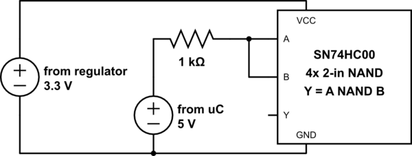
I have the following circuit:

simulate this circuit – Schematic created using CircuitLab
The SN74HC00 (from TI) has input clamps, so I am expecting the 5V logic input to be clamped to about 3.3V at pins A and B, and (5-3.3)/1000 = 1.7 mA to flow through the resistor.
In stead, I measure 4.5V at pins A and B, and even VCC now measures 4.5V! (The resulator is probably not happy with this, and is sinking current).
If I remove the SN74HC00 from its socket, the voltage at the regulator's output returns to 3.3V .
Later, I put the SN74HC00 back, disconnected the 3.3V supply from VCC, but kept the 5V input connected. VCC still measured 4.5V .
I also tested this with an M74HC00 (from ST micro) (whose datasheet does not mention clamping), expecting it to break. Same results, and the chip still works with 5V supply.
What is wrong with this circuit? Why does it not clamp the input?
