1
\$\begingroup\$

my question is how I decide my ground reference in a circuit when only using batteries.

Let's say I'm using a battery pack with slots for up to 2 AA 1.5V batteries, creating 3V. In this case, I will use 3 of these batteries packs in this circuit. Two of them will be connected in series, creating 6V and one will be standalone.

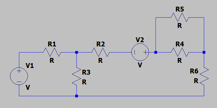
Using this picture to describe my scenario. If my V1 has 6V (Two battery packs in series), and my V2 has 3V (Only one battery pack)

Where will my ground be (do I decide it?), is it under V1 (negative pole) or can it be in the same terminal as the negative pole of V2?

If I wanted to measure the voltage at any point of the circuit, what will I use as a reference?

enter image description here

This is what a battery pack is

enter image description here

\$\endgroup\$
4
  • 1
    \$\begingroup\$ why do you want to do this? \$\endgroup\$ Commented Oct 12, 2020 at 19:42
  • 1
    \$\begingroup\$ You can freely choose any point you want as the 0V ground reference. Or for 1 kilovolt reference. It does not change any voltage differences or currents in the circuit, just the absolute value. \$\endgroup\$
    – Justme
    Commented Oct 12, 2020 at 19:52
  • 1
    \$\begingroup\$ My ‘63 MGB had 2 x 6V batteries with + gnd, now obsolete due to better cathode anti-corrosion \$\endgroup\$
    – D.A.S.
    Commented Oct 12, 2020 at 19:54
  • \$\begingroup\$ Looks like a homework problem. Just pick any point as the "ground reference" and be consistent. \$\endgroup\$
    – Aaron
    Commented Oct 12, 2020 at 20:46

2 Answers 2

1
\$\begingroup\$

Unless you have a reason to do otherwise, it's a modern convention to use the negative lead of the battery pack or power supply as your ground node.

Unless you rely on actual physical properties of ground, eg, for radio, or to bond to a conductive housing, in a way it does not even matter.

Most uses chose the negative terminal, but a few legacy vehicles have had a positive chasis ground. And some long range telecom power feeds use positive ground under the idea that cathodes suffer less electrolytic degradation than anodes.

In terms of your circuit, the design is heavily inspired by the idea that the negative power supply will be ground and the reference point for all measurements. Notice how the components break up the positive paths, but not the negative, which is left consistent as a single node? It would be entirely possible to design a functionally equivalent circuit which instead maintained the integrity of the positive path for easy analysis relative to that, but it is not what the designer did. Hence we can see that the designer was displaying at least an unconscious, habitual assumption of the idea of a negative ground.

(One exception to the idea of circuit designs tilted towards ground integrity is the common use of semiconductor low side switches to switch the ground side of a load; even though it makes a circuit drawn from a negative ground perspective less clear, this is done because N-FETs are more efficient switches than their positive channel counterparts)

\$\endgroup\$
-1
\$\begingroup\$

“Ground” is always defined in electronics as zero voltage, just like earth-ground.

  • for floating supplies, it is arbitrary yet the convention is still V- rather than V+. For bipolar supplies 0V , it is normally in between V+/V- with 3 terminals.
\$\endgroup\$

Your Answer

By clicking “Post Your Answer”, you agree to our terms of service and acknowledge you have read our privacy policy.

Not the answer you're looking for? Browse other questions tagged or ask your own question.