1
\$\begingroup\$

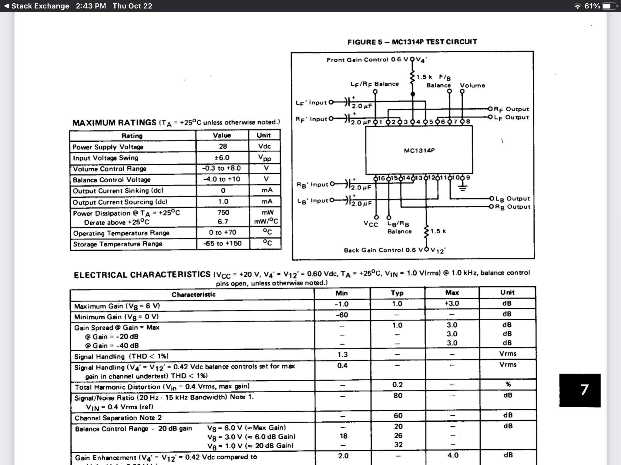
I have an old quadraphonic system with a problem that I've traced to what I think is an MC1314. (That's not the question.) So I ordered a replacement, popped in and it didn't solve the problem. I decided to make a test circuit based on the data sheet (available here https://datasheetspdf.com/pdf-file/570328/Motorola/MC1314P/1 on page 4 with notes on page 11.) Here's the circuit I bread boarded: MC1314 Test Circuit
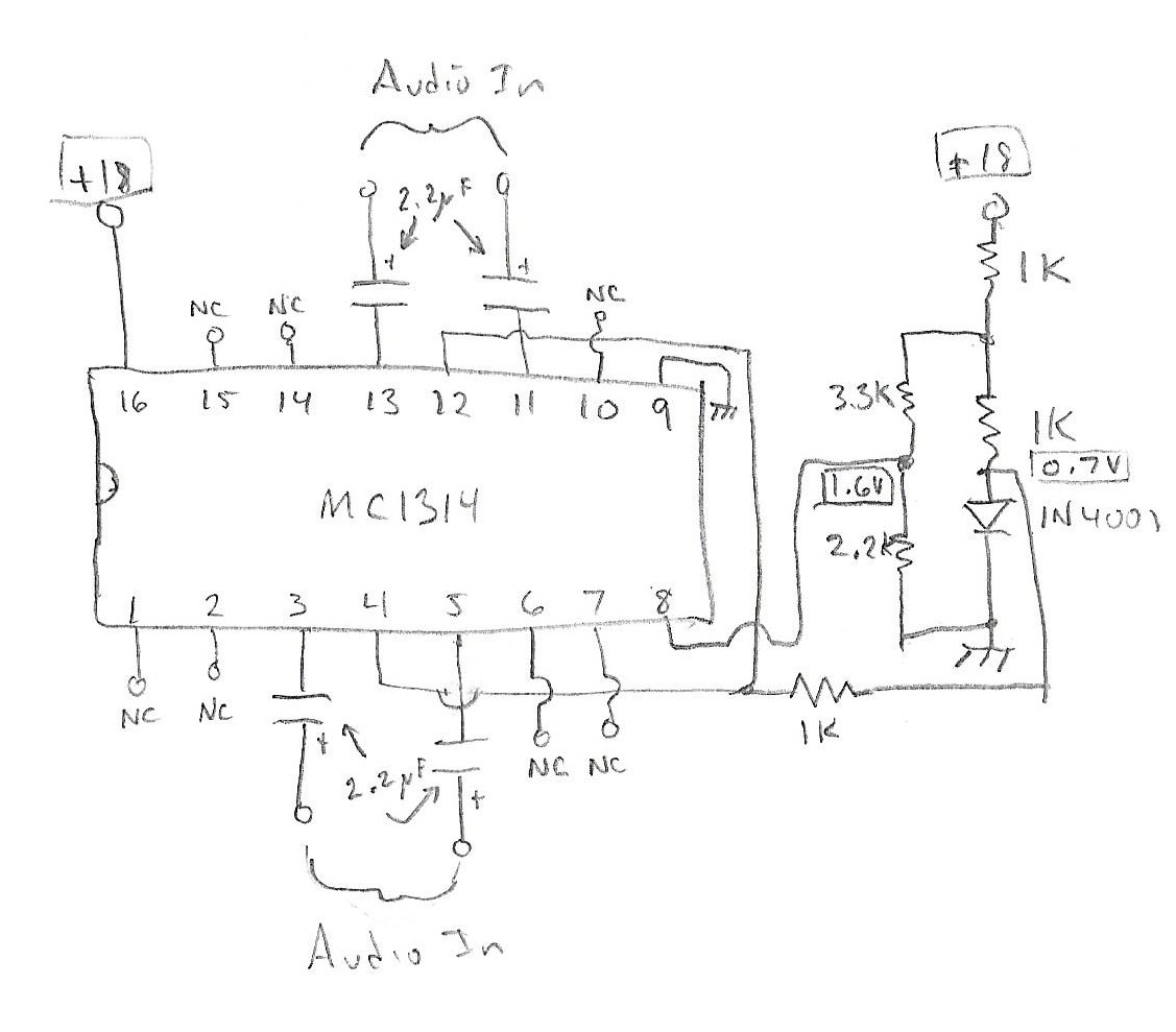
The +18V was two 9V batteries in series. Anyway, I plugged it in and blew the IC. That leads me to suspect that 1) I screwed something up, or 2) The chip was bad, or 3) The chip actually wasn't an MC1314 or 4) The chip was an MC1314, but Motorola has recycled the number. I haven't found any evidence of #4, seeing as how I ordered it from eBat #2 or #3 are also possible, and since I'm human, #1 is always a leading possibility. Edit: What could have gone wrong?

\$\endgroup\$
7
  • \$\begingroup\$ A datasheet would help for this 4 channel VCA \$\endgroup\$
    – D.A.S.
    Commented Oct 22, 2020 at 18:22
  • 1
    \$\begingroup\$ @Duston: You left several inputs and outputs disconnected. It's possible it started oscillating and destroyed itself. That's just guessing, though. \$\endgroup\$
    – JRE
    Commented Oct 22, 2020 at 18:30
  • 1
    \$\begingroup\$ @TonyStewartSunnyskyguyEE75 The question includes a URL to the datasheet. \$\endgroup\$
    – Duston
    Commented Oct 22, 2020 at 20:04
  • \$\begingroup\$ @JRE On Page 11 the notes say that "If xxx is unused, leave the pin open." Also, 4 of the open pins are audio output. \$\endgroup\$
    – Duston
    Commented Oct 22, 2020 at 20:04
  • \$\begingroup\$ The caps blew the input transistors \$\endgroup\$
    – D.A.S.
    Commented Oct 22, 2020 at 20:18

2 Answers 2

1
\$\begingroup\$

I'm answering my own question because the issue is now moot. I bought another MC1314, installed it in the stereo and it's working correctly, so a test circuit is no longer needed. Thank you for your help.

\$\endgroup\$
0
\$\begingroup\$

https://datasheetspdf.com/pdf/570328/Motorola/MC1314P/1. For the quad VCA obsolete chip.

Your schematic on the surface looks ok.

Did it overheat immediately? Polarity correct on Vcc, Gnd

https://4donline.ihs.com/images/VipMasterIC/IC/MOTO/MOTOS12755/MOTOS12755-1.pdf?hkey=D9A213CC6FEE7D103EF6B88F2AEB20B8 enter link description here

enter image description here

Beware the pins are shown upside down in the block diagram!

ALSO your cap polarity is backwards

which shorts out the cap!! And may induce excessive DC bias current (?)

why did it blow?

tl;dr = e-caps reversed, causing caps to conduct DC with low ESR, causing differential input Vbe of NPN’s to go negative with 0Vin and +ve emitters, causing Reb=~<10 ohms, causing avalanche punch-thru, causing Vce punchthru and unlimited current across conducting junctions, causing explosive results

  • with >10W/sqmm causing a crater in the epoxy but perhaps not sustained long enough to blow the e-caps which might have been a bigger explosion with toxic smoke , And;It enough to exceed say a battery thermal runaway which would result in a bigger problem.

  • most BJT’s have a -5V limit for Vbe.

  • many e-caps can tolerate -10% of the forward rated voltage for a limited period.

  • when you aren’t sure try to have current limiting for the size of the junction, BJT or IC or PCB.

  • use a passive RC filter or PTC oxide resistor for the safe limit might work if it heats up faster and rises in R faster than the junction,

  • but not in this case.

  • an active current limiter is pretty easy to setup for experimentation or use an LDO sized appropriately, e.g. LM317

Reading material

https://www.onsemi.com/pub/Collateral/AN1628-D.PDF

\$\endgroup\$
8
  • \$\begingroup\$ I'm certain I got the Vcc polarity correct. You're right the capacitors are backward, I made a bad assumption. I had the signal (1kHz, 200mV peak) applied. I'm not sure how much (if any) DC is in that signal. \$\endgroup\$
    – Duston
    Commented Oct 22, 2020 at 20:12
  • \$\begingroup\$ @Duston is the internal bias that might be damaged by reverse Vbe<-5V from 0Vdc input, but it wouldn’t get hot then you didn’t say if it did ...”blew. IC?” Symptoms?? \$\endgroup\$
    – D.A.S.
    Commented Oct 22, 2020 at 20:19
  • \$\begingroup\$ "Blew IC" means a pop and smoke. \$\endgroup\$
    – Duston
    Commented Oct 23, 2020 at 13:02
  • \$\begingroup\$ @Duston how entertaining, a negative resistance detonation with a crater of epoxy and rather toxic carcinogenic fumes. Too bad. A PTC is good thing to experiment with. \$\endgroup\$
    – D.A.S.
    Commented Oct 23, 2020 at 13:07
  • \$\begingroup\$ Now that I look at the data sheet again, I see two schematics that include the capacitors on the inputs. The sample circuit with the the whole chipset on Page 9 shows the - of the capacitors on the 1314 inputs (that's why I oriented them that way.) . The test circuit on Page 4 shows them the other way around. I'm pretty sure the stereo itself also has the - on the 1314 inputs. \$\endgroup\$
    – Duston
    Commented Oct 23, 2020 at 19:14

Your Answer

By clicking “Post Your Answer”, you agree to our terms of service and acknowledge you have read our privacy policy.

Not the answer you're looking for? Browse other questions tagged or ask your own question.