1
\$\begingroup\$

I have a motor controller that outputs a fault by pulling down its I/O pin (PIN 10). It will also go into fault if you external pull the pin down too.

The MC has two configurable pullups: A: The output pin is pulled high by a 100K resistor @ 30V. B: The output pin is pulled high by a 1K resistor @ 6V.

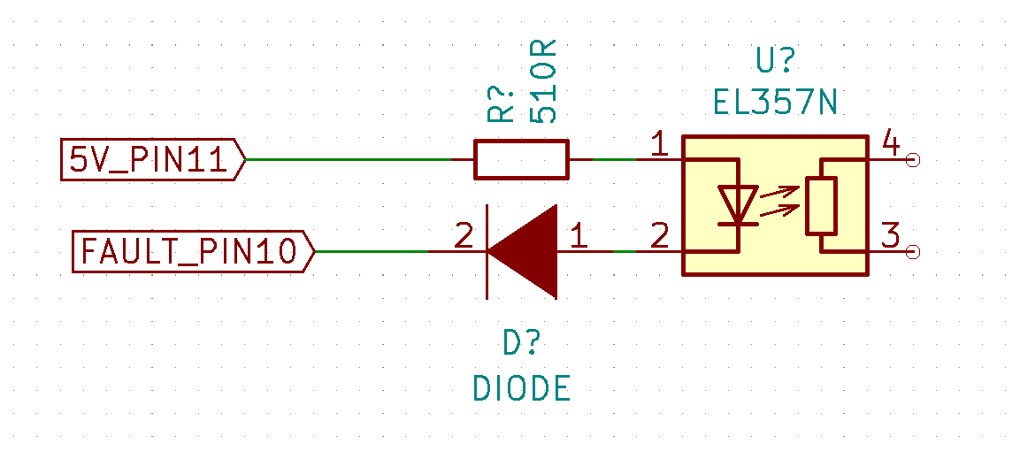
I require an isolated method of monitoring this voltage, my solution is to use an optoisolated that is supplied by the motor controllers 5V output via a 510R resistor.

When the motor controller goes into fault, it will pull down to the ground and turn on the opto. A diode prevents backfeeding of the 6V (B)/ 30V (A) into the motor controllers 5V rail.

I have tested this and it is working, but is there any negatives, or better solutions?

Diagram

\$\endgroup\$
6
  • \$\begingroup\$ If the FAULT signal can only pull down, the diode isn't necessary. \$\endgroup\$
    – Mattman944
    Commented Oct 27, 2020 at 12:56
  • \$\begingroup\$ There is a 100K pullup that takes the Fault line up to 30V, im hoping the diode will give some form of isolation between the two voltage rails? \$\endgroup\$ Commented Oct 27, 2020 at 13:04
  • \$\begingroup\$ OK, if there is a pullup to 30V, then the diode is necessary. \$\endgroup\$
    – Mattman944
    Commented Oct 27, 2020 at 13:48
  • \$\begingroup\$ The resistor value seems a little high to me (only about 6 mA). There is no way for us to know without knowing what the circuit on the right looks like. Have you used the transfer characteristics in the spec to analyze what will happen to the opto transistor? \$\endgroup\$
    – Mattman944
    Commented Oct 27, 2020 at 13:56
  • \$\begingroup\$ In the title you mention that "ground can swing between 30V and 0V", but in the body you never mention or explain this. Which ground (which side of the opto)? What reference are you using when you say the ground voltage is "swinging"? \$\endgroup\$
    – The Photon
    Commented Oct 27, 2020 at 15:37

1 Answer 1

1
\$\begingroup\$

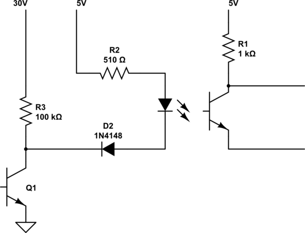
I believe that your circuit looks like this:

schematic

simulate this circuit – Schematic created using CircuitLab

Calculate the current in the opto diode. The opto diode has a drop of roughly 1.3V, the plain diode has a drop of about 0.7V:

= (5.0 - 1.3 - 0.7) / 510 = 5.9 mA

Calculate the current in the opto transistor. Vce at saturation will be about 0.3 V.

= 4.7 / 1k = 4.7 mA

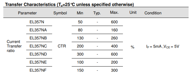
You need a transfer percentage (transistor current / diode current) of:

= 4.7/5.9 = 80%

Now, look at the transfer characteristic table. EL357N (with no letter after it) isn't guaranteed to work. The "A" device is marginal.

If you are using the higher gain part and there is no chance you will ever use a lower one, then you are fine.

But, consider this, one concept that I try to teach young engineers: when margin is cheap, put in a lot. And here I mean cheap in the broadest sense, not just cost. Unless overall power is a concern, make R2 smaller for more margin.

enter image description here

\$\endgroup\$
1
  • \$\begingroup\$ Thank you for your response, CTR is a new concept for me but make sense with your explanation. I assume I need to calculate the value of R2 to below the minimum CTR to guarantee the 4.7ma current of the transistor. If I change R2 to 210r the current in the Opto diode is 15ma which would produce a CTR value of 31% \$\endgroup\$ Commented Oct 28, 2020 at 19:19

Your Answer

By clicking “Post Your Answer”, you agree to our terms of service and acknowledge you have read our privacy policy.

Not the answer you're looking for? Browse other questions tagged or ask your own question.