1
\$\begingroup\$

From my understanding the bandwidth of an input signal to an ADC is defined as the range of frequencies the signal consists of, which is calculated as the difference between the highest and lowest frequency within the signal band. So ok, but what about a time to digital converter (TDC)? How can one define the bandwidth here?

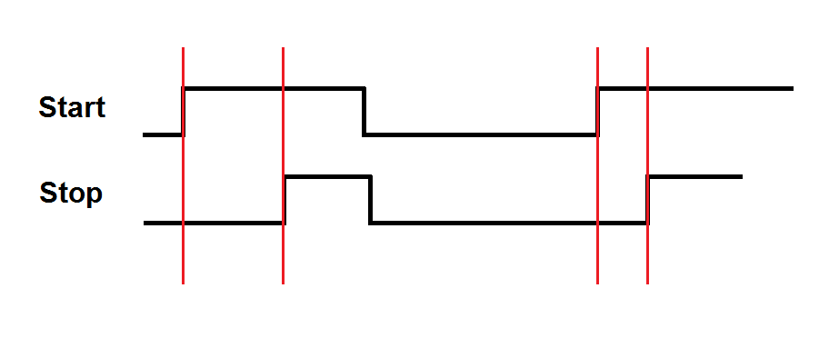
A TDC takes in two inputs, usually called Start and Stop signals, and measures the time difference between the two. For example, the input stream might be like this

enter image description here

What does input signal bandwidth mean here?

EDIT

What confuses me is this Sigma-Delta TDC paper for example. It says:

In the MASH Sigma-Delta TDC, there is also a special relation between the OSR and full scale input range. The bandwidth of the input signal, BW, is set to 100 kHz in this design. The sampling clock of the TDC system is then equal to 2 BW OSR. Due to the input signal’s timing nature, the peak-to-peak full scale input signal amplitude has to be smaller than one period of the sampling clock.

Now according to this, if OSR=25, the system clock is found to be 5MHz, which means that the PP FS input range has to be smaller than 200ns.So not sure what the physical interpretation of BW is here.

In another paper I found a comparison table which compares different architectures: enter image description here
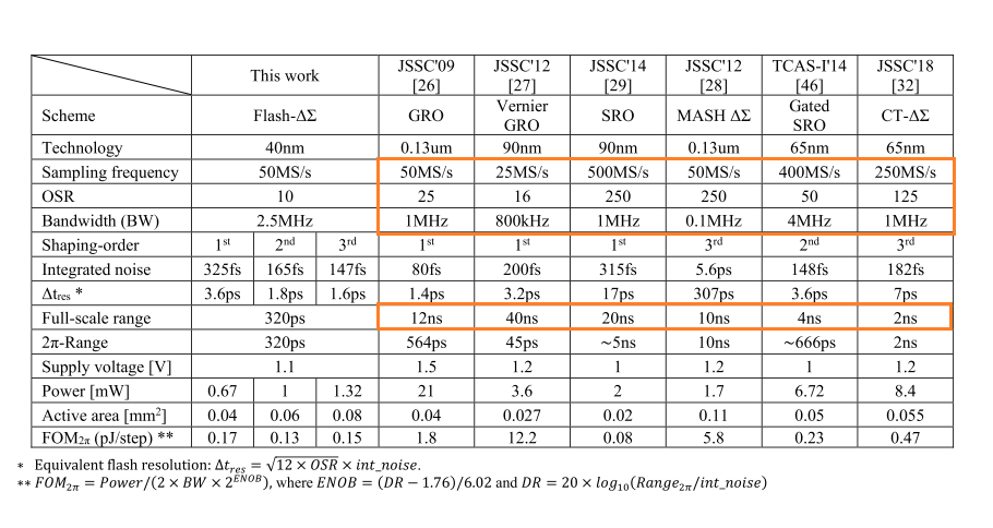
The papers indexed 26 and 28 have the same 50MS/s sampling frequency, but the BW in former case is 10 times more. The FS input range in both cases is more or less the same. Anyway, I cannot turn my head over how or in what manner BW could limit system performance?

\$\endgroup\$
4
  • \$\begingroup\$ How often does the start and stop pulses happen every second? \$\endgroup\$
    – Andy aka
    Commented Nov 26, 2020 at 8:39
  • \$\begingroup\$ @Andyaka For example in an ADPLL the Start signal is the reference signal, which might be 4-50MHz, while the stop signal is the DCO output frequency which is somewhere between 1-2GHz. \$\endgroup\$
    – dirac16
    Commented Nov 26, 2020 at 9:03
  • \$\begingroup\$ That, to me, is your answer then and presumably both have the same rate - it's rate I asked for because having a start signal then two or more stop signals before the next start signal is going against your diagram. \$\endgroup\$
    – Andy aka
    Commented Nov 26, 2020 at 9:04
  • \$\begingroup\$ Dirac, have you done with this question now? Were my answer and mkeith's answer of no use at all? \$\endgroup\$
    – Andy aka
    Commented Dec 23, 2020 at 15:03

3 Answers 3

3
\$\begingroup\$

'Bandwidth' is one of those words that gets applied to many different things, so it doesn't have a concrete, context-free, definition.

With a TDC, one context is the maximum and minimum frequencies that can be applied to the inputs, and still have the timing behave properly.

Another one is the reciprocal of the smallest time difference that can be resolved between the edges. Of course you need to consider the difference between resolution and accuracy here.

It's also worth considering this context when thinking about metastability in latches, that you need a bandwidth approaching infinity if you are going to resolve the difference between a data edge being before or after a clock edge by an infinitessimal amount. In fact when designing a TDC, metastability in the input circuitry is a key concern.

Yet another context is the rate at which successive readings are taken, which may be the same as input frequency, but need not be. This controls the bandwidth of phase modulation on the signal can be detected. Even if there is no deliberate phase modulation, phase noise from large offsets will be aliased down to baseband.

\$\endgroup\$
0
\$\begingroup\$

One way to look at it, especially considering that you are feeding the signal to an ADC, is what bandwidth is required to accurately reproduce the input signal. There is a kind of rule of thumb that the bandwidth of a rising edge is:

BW = 0.35/RT

Where BW is the bandwidth and RT is the rise time. If BW is in GHz, then RT can be in nanoseconds.

The bandwidth of a fast rising edge can be pretty high.

There are mathematically rigorous definitions of bandwidth. But sometimes people speak casually about it, too. Like Neil says.

\$\endgroup\$
0
\$\begingroup\$

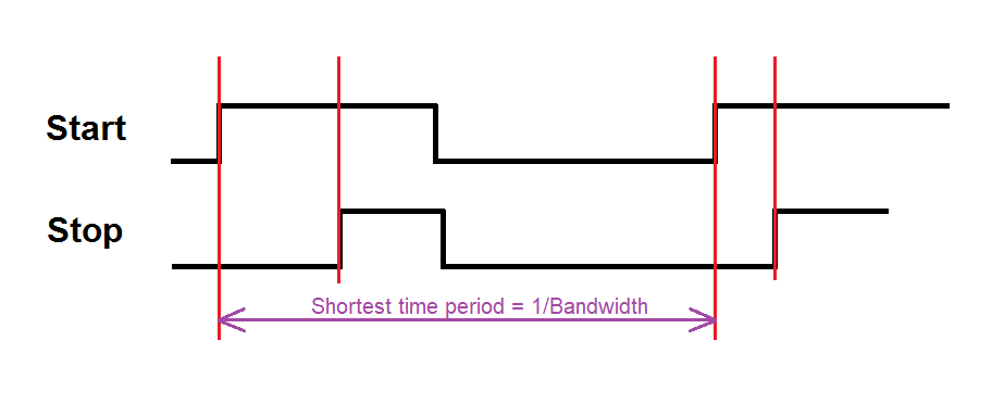
I see it like this: -

enter image description here

Or you could make an argument that the bandwidth is \$\dfrac{\text{shortest time period}}{2}\$

This assumes that the longest time period is infinity. The longest time period defines the lower operating frequency of the bandwidth.

In other words, if you do not calculate the time difference for every occurance of a start/stop situation, the values will have the possibility of being aliased.

Hence it is the frequency of your stop (or start) signal that determines your bandwidth.

\$\endgroup\$

Your Answer

By clicking “Post Your Answer”, you agree to our terms of service and acknowledge you have read our privacy policy.

Not the answer you're looking for? Browse other questions tagged or ask your own question.