0
\$\begingroup\$

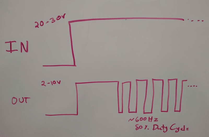
I'm looking to make a circuit that takes a 20-30VDC input and, when that goes high, generates a signal that also goes high, but to a different voltage (2-10VDC). Then after some time of being high (on the order of hundreds of milliseconds to seconds), I want it to transition to a ~600Hz, ~50% duty cycle PWM.

I'm thinking of a monostable 555 and an astable 555 with the outputs into an or gate. Powered off a linear regulator to drop down the input voltage. This seems a bit inelegant. Any other concepts of how this might get accomplished?

enter image description here

\$\endgroup\$
3
  • 4
    \$\begingroup\$ One word: Microcontroller. \$\endgroup\$
    – Bort
    Commented Dec 18, 2020 at 21:01
  • \$\begingroup\$ Might be a good use for a 555. Try it and see. \$\endgroup\$
    – rdtsc
    Commented Dec 18, 2020 at 21:04
  • \$\begingroup\$ Can the 30 V signal source enough current to power the oscillator circuit? 5-10 mA, maybe? If yes, I have a solution with one 555 and only 5 external components. \$\endgroup\$
    – AnalogKid
    Commented Dec 19, 2020 at 0:12

4 Answers 4

0
\$\begingroup\$

Assuming you don't want to use a microcontroller, I'd simplify it a bit by using just a single astable 555 with suitable enable logic.

Feed the incoming signal into a schmitt trigger or similar to produce a logic signal. Feed the logic signal into the input of an RC filter tuned to create your delay. Feed the delayed signal into a transistor that shorts the timing cap of the 555 until the signal is asserted.

While the timing cap is shorted the 555 will just go high, then once the timing cap is no longer shorted the 555 will start producing the square wave. Pull the output of the 555 up to your output voltage through another transistor.

\$\endgroup\$
3
  • \$\begingroup\$ Many of these answers are useful, but this one makes the most logical sense to me. Except... Why use the schmitt trigger initially, just to bring the voltage in range? Then with the RC filter, should we use another schmitt trigger after it to make sure the transistor goes on hard instead of slowly? \$\endgroup\$
    – matth
    Commented Dec 21, 2020 at 17:16
  • \$\begingroup\$ Good point on the first schmitt trigger. Maybe only one would be required before the transistor. Would need some analysis to figure out the details. \$\endgroup\$ Commented Dec 22, 2020 at 19:47
  • \$\begingroup\$ I just tested out the timer circuit portion of this concept by simply manually shorting that cap, and it worked beautifully. I think we have a winner. \$\endgroup\$
    – matth
    Commented Dec 23, 2020 at 14:59
1
\$\begingroup\$

yes, micro.

You could conceivably do it with a single 600Hz clock (could well be 555) and a counter(74xx or 4060) to count out pulses for the initial 100%-on-phase. You could use one or more 74xx flip flops for gating, maybe an inverter or nor gate to stop the counter after the initial phase is over and reset it at the start. Needless to say this doing it the hard way.

The final output level would involve an opamp and probably a transistor if you're actually using this to drive something.

PS- is this a solenoid drive circuit with a startup boost? they have single chips that do all this, like DRV101 etc

\$\endgroup\$
2
  • 1
    \$\begingroup\$ Agree with the DRV101 (actually 103, I think 101 is obsolete), one chip does it all, with driver, PWM delay, freq, and duty cycle etc...no code programming. \$\endgroup\$
    – P2000
    Commented Dec 19, 2020 at 0:16
  • 1
    \$\begingroup\$ This is not a solenoid drive exactly, but essentially it's the same thing. Actuating a different device the same way. I never knew these chips existed. Thanks! \$\endgroup\$
    – matth
    Commented Dec 21, 2020 at 17:09
0
\$\begingroup\$

Microcontrollers make doing these stuff really easy to be honest!

Take this as an example:

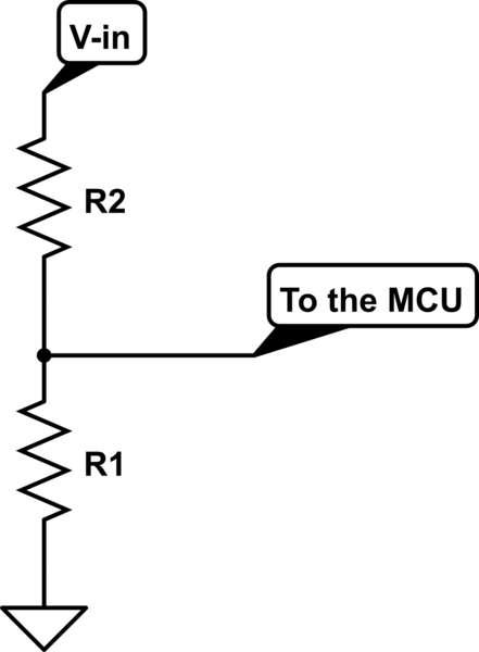
The input is connected to your microcontroller like this:
schematic

simulate this circuit – Schematic created using CircuitLab

This is a voltage divider, and the ratio works like this(to a good approximation):

Vout/Vin = R1/(R1+R2)

2 things to note here:

  1. This is rather a very simple way and not very efficient for that matter, but larger resistors (to an extent) would do the trick.
  2. MCU should not be connected to live lines, it's a good practice not to at least! so if that input voltage is not isolated, you do need to take care of that.

A much better way, for instance, would be to trigger the microcontroller through a transformer when the transition from 0V to the peak voltage happens (look at impulse response), then you have isolated your input and saved power, but you cannot leave the input on for too long, other wise it might damage the transformer (might wanna use a cap in series with your transformer)! lot of other ways out there(optocouplers in general), but I'd rather stick to the basics.

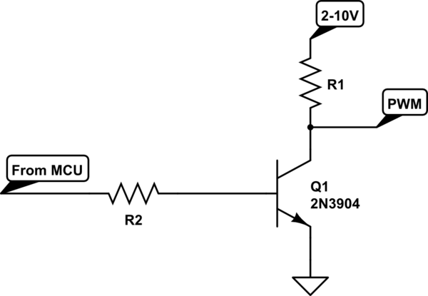
Then, you can use a transistor to make your PWM signal:
schematic

simulate this circuit

Important thing to note here: The type of the transistor you use would depend on your load, the amount of current and these stuff. but if you are trying to drive a motor or sth similar, there are chips with built-in comparators for generating PWMs and a push-pull output.

P.S: I don't know how you are thinking of getting the 2-10V peak (batteries?) for your output, but if one power source is to be used, you ought to think about converting that 20-30V into the 2-10V range. look into DC-DC converters for that matter.

\$\endgroup\$
0
\$\begingroup\$

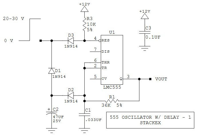
This is a first pass at the circuit I mentiioned, modified for an independent 12 V power source. R1-C1 set the output frequency, and driving them with the output assures a near-perfect 50/50 output duty cycle. D2 acts as a switch to include C2 during the first half-cycle for about 1.5 s. R3-D3 allow a 30 V signal to reset a 12 V chip without damage, and D1 discharges C2 between activations.

When the input signal goes high, the 555 comes out of the reset state and the output goes high. The output was low so C1 was discharged, and C2 was discharged through D2, so the output goes high immediately and starts charging both C1 and C2. After about 1.5 s, the R1-C1-D2 node rises above the Threshold input transition voltage, and the output goes low as the circuit begins to oscillate.

C2 remains charged up so it no longer has a significant effect on the output frequency. It is "topped off" at the beginning of each positive half-cycle, but this should appear as a very small additional capacitance. If the circuit off time between activation cycles is a few seconds, D1 can be replaced with a high-value resistor to completely remove C2 from the oscillator after the first half-cycle. If the off time is not long enough to discharge C2 that way, leave in D1 and place a 1 M resistor in parallel with it.

enter image description here

\$\endgroup\$

Your Answer

By clicking “Post Your Answer”, you agree to our terms of service and acknowledge you have read our privacy policy.

Not the answer you're looking for? Browse other questions tagged or ask your own question.