0
\$\begingroup\$

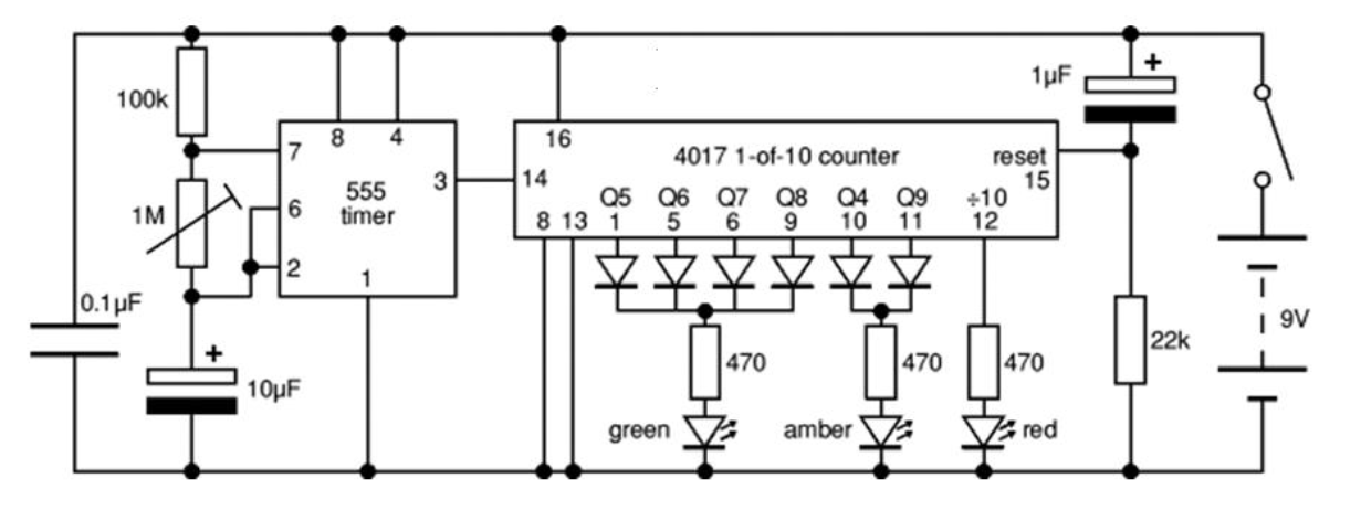
I have the following circuit enter image description here

It's a basic traffic light circuit using a 555 timer and decade counter. All works fine but what is the purpose of the 0.1 microfarad capacitor on the left of the diagram? As far as I can see it's doing nothing. If I remove the capacitor or replace it with a 10 microfarad or 100 microfarad nothing changes.

This diagram has been provided to me so guessing that it does serve a purpose but what is it?

Thanks

\$\endgroup\$
3
  • \$\begingroup\$ It's a decoupling capacitor for one or both of the IC's. I'd add a second one, so each IC has it's own. You're supposed to place them close to the IC they're decoupling and use as short traces as possible. \$\endgroup\$ Commented Dec 19, 2020 at 14:59
  • \$\begingroup\$ Decoupling capacitors on power supply rails are considered good design practice. But in this circuit - with it running off of a battery and using (by today's standards) slow parts (output rise and fall times around 50 ns with a 9V supply) - it probably is not really needed, as you noted. \$\endgroup\$
    – SteveSh
    Commented Dec 19, 2020 at 15:19
  • \$\begingroup\$ Decoupling caps become more important 1) as clock rates and edge speeds increase and 2) with noisy power supplies and/or sensitive analog circuits. \$\endgroup\$
    – SteveSh
    Commented Dec 19, 2020 at 15:21

2 Answers 2

1
\$\begingroup\$

It is called a decoupling capacitor.

Real wires and traces aren't perfect lines on a page that perfectly connect two components together. They have inductance which produces voltage drops and voltage spikes when the component's current demand changes due to wire inductance between the component and the battery. So you can stick an inductor in the middle of every wire/trace line on that schematic.

The capacitor is placed as close to the component as possible with minimal trace length and (something not shown on a schematic) and acts as a local power supply to get around this.

It's the kind of thing where if the circuit is undemanding and tightly built, you may get away without it. But demanding or messily build circuits won't work at all without it and even if the circuit runs without it, it will run better and quieter with it.

If it is required but missing, the circuit may outright not work at all, work some of the time but not all of the time, or exhibit very strange behaviours. There's almost no point to debugging a circuit without decoupling capacitors until decoupling capacitors are added.

\$\endgroup\$
0
\$\begingroup\$

Its filtering high frequency signals away and also stabilizes the supply voltage for the NE555. Supply wires have resistive voltage drops and thus other loads on the same wire can create supply voltage variations. Further supply wires are forming inductive loops and capacitive couplings. That's the pathway other electrical items can have some impact. For the capacitor a regular commercial circuit designer would have added a note for the layout creator of the form: "Place close to part XY". If looking for older logic boards or maybe the classic C64 mainboard then you will find lots of this little capacitors, each one close to the vcc/gnd pins of the semiconductors on the board.

\$\endgroup\$
2
  • \$\begingroup\$ If you use capital letters to begin each sentence it will make your answer much more readable. You might also add apostrophes for "it's" (meaning it is) and "that's" (meaning that is). \$\endgroup\$ Commented Dec 19, 2020 at 15:23
  • \$\begingroup\$ @ElliotAlderson - i was just sort of teletyping, i am sorry and will watch for it in the future. \$\endgroup\$ Commented Dec 19, 2020 at 15:29

Your Answer

By clicking “Post Your Answer”, you agree to our terms of service and acknowledge you have read our privacy policy.

Not the answer you're looking for? Browse other questions tagged or ask your own question.