1
\$\begingroup\$

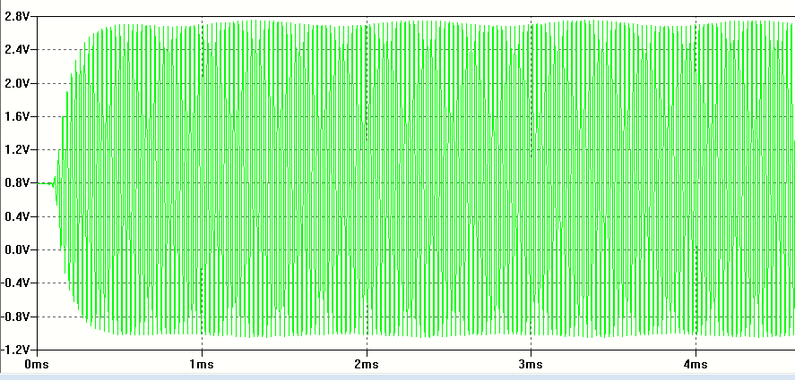
I have a wave with ~ <10% modulation. Is there any way to amplify the envelope of a signal at the envelope demodulator end? You can barely make out the envelope in the image below but I think I need to amplify this otherwise the diode will be in an "off" position and it doesn't demodulate the signal.

enter image description here

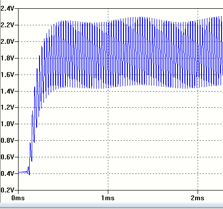
This is the output of my envelope detector using the above waveform as the input

enter image description here

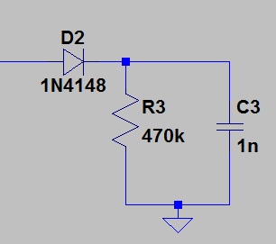
A schematic of my envelope detector can be found below enter image description here

\$\endgroup\$
11
  • \$\begingroup\$ Assuming AM (which seems true looking at your green colors there) it seems to me that if the carrier is sufficiently strong, you should be fine. Just amplify after detection and removal of the RF. I think you fail to understand the process. But it could just be me. Can you write more about why you think that less than 10% modulation causes the diode to be "off" and your diode won't detect the tuned RF into something usable? \$\endgroup\$
    – jonk
    Commented Jul 4, 2017 at 5:43
  • \$\begingroup\$ @jonk That's a hunch I have. I just used a basic envelope detector using a diode and a low pass filter to try and grab the 1kHz audio tone. When connecting that signal shown in green in my question to the envelope detector, it doesn't seem to have demodulate it properly (looks like the diode is in the off position all the time). I'll post an image of output of my envelope detector \$\endgroup\$
    – Guy Lee
    Commented Jul 4, 2017 at 5:59
  • 1
    \$\begingroup\$ Actually when I think about it, it might even be due to the fact that my time constant RC might be too small because you can (just barely) see the saw tooth wave distortions. \$\endgroup\$
    – Guy Lee
    Commented Jul 4, 2017 at 6:10
  • \$\begingroup\$ I think you need to disclose some schematics now. I'd like to see your detector, RF filter, etc. (I assume you are feeding your input with a data file?) What's the R? What's the C? etc. \$\endgroup\$
    – jonk
    Commented Jul 4, 2017 at 6:30
  • \$\begingroup\$ Separating the 1 kHz 10% modulation from a 38 kHz carrier will require a low-pass filter more complex than a simple RC type. \$\endgroup\$
    – glen_geek
    Commented Jul 4, 2017 at 14:07

1 Answer 1

1
\$\begingroup\$

Take that signal, run thru a limiter, and multiply the two signals in a mixer, with low-pass-output filtering.

\$\endgroup\$
2
  • 1
    \$\begingroup\$ So basically product demodulation/ detecting? \$\endgroup\$
    – Guy Lee
    Commented Jul 4, 2017 at 23:21
  • \$\begingroup\$ At 38KHz, a fast limiter will have low nanoseconds delay, thus little phase shift. With 1volt PP signal, a simple bipolar diffpair will suffice to limit, that output being used to drive the LO inputs of the mixer. Consider the NE602. \$\endgroup\$ Commented Jul 11, 2017 at 13:31

Your Answer

By clicking “Post Your Answer”, you agree to our terms of service and acknowledge you have read our privacy policy.

Not the answer you're looking for? Browse other questions tagged or ask your own question.