0
\$\begingroup\$

I have an Arduino project that consists of a motor and a solenoid valve, but I want to use a Raspberry Pi because it seems to be easier to make it communicate with my computer because it has built in wifi. I want to be able to control the microcontroller/raspbi with a code in my computer.

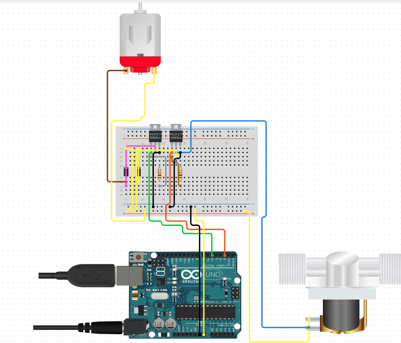
I've never connected my Raspberry Pi to a circuit board. Is it possible to use the same circuitry while slightly adjusting the input/output lines? Or will that damage everything? Here's the image
\$\endgroup\$
5
  • 1
    \$\begingroup\$ Electrically, maybe. It would help if you were to show your circuit diagram. On the other hand, if you expect to plug an Arduino "shield" onto to a Pi, then that won't work - not just electrically, but also mechanically. Add some details about what you have and what you are doing. \$\endgroup\$
    – JRE
    Commented Jan 30, 2021 at 9:19
  • \$\begingroup\$ I edited the question. What are your thoughts? \$\endgroup\$ Commented Jan 30, 2021 at 10:18
  • 1
    \$\begingroup\$ You've posted a wiring diagram (or cartoon, as they are known around here) but we use schematic diagrams to understand the schema of the circuit. Check the GPIO voltages of each device. If they're the same you should be OK. If not then modifications will be required. \$\endgroup\$
    – Transistor
    Commented Jan 30, 2021 at 10:40
  • 1
    \$\begingroup\$ @JoshuaPark: It looks like you are using Fritzing. It produces wiring diagrams by default. Wiring diagrams make it easy to wire circuits, but they obscure the function of the circuit. Anyone who wants to help you has to first convert your wiring diagram to a schematic diagram. Fritzing can produce schematic diagrams. Since you have the original file, it is easier for you to produce the schematic than for everyone to trace your circuit. That's why we put some much emphasis on schematics here. \$\endgroup\$
    – JRE
    Commented Jan 30, 2021 at 11:25
  • 1
    \$\begingroup\$ It's not clear what you mean by "slightly adjusting" your IO lines but keep in mind that the Uno that you've drawn has 5V logic signals on its IO pins and the Pi uses 3.3V logic and its inputs are NOT 5V tolerant. So you will need to adjust accordingly. \$\endgroup\$
    – jwh20
    Commented Jan 30, 2021 at 11:37

1 Answer 1

1
\$\begingroup\$
  1. Your diagram shows power to the motor and solenoid coming from the Arduino Vin. The Raspberry Pi has only a 5V supply. Your motor and solenoid will probably need a separate power supply when used with the Pi.
  2. The MOSFETs you have (looks like 30N06L) will work with 5V, but I have seen posts from other folks suggesting that the 30N06L doesn't (quite) work with 3.3VGS. It may work OK(ish) or it might not. It depends to some extent on your load. Some 30N06L also just work a little better at lower VGS than others.

You're going to have to change at least the power source for the motor and solenoid, and you may need to use a different MOSFET.

\$\endgroup\$

Your Answer

By clicking “Post Your Answer”, you agree to our terms of service and acknowledge you have read our privacy policy.

Not the answer you're looking for? Browse other questions tagged or ask your own question.