0
\$\begingroup\$

I have a RS422 non-multidrop connection between two connectors on a PCB (CLK+/- and DATA+/-) clocked at 1MHz, and currently routed with adapted edge-coupled microstrips (120Ohm differential impedance).

I would like to add measurement stubs, for example with oscilloscope probe tip connectors - but without degrading the quality of the bridge I am measuring.

The existing connection is about 10cm long, but the measurement stub will have to be 20 to 30cm long to reach a maintenance panel.

  • Because of the way the PCB is designed, I cannot just add testpoints ON the existing RS422 connection.
  • I thought about designing microstrips with differential impedance much greater than the signal I want to measure and leave the testpoint not terminated, but it's impossible for me to go above 350 Ohm.
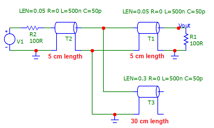
  • I also thought about making a 120Ohm stub terminated with a 240Ohm resistor (since the equipment is not multi-drop, I suspect it won't handle 2 stubs with 120Ohm termination each - more likely to handle 50% more load), which currently is my baseline but I'm worried about the reflections from the 120->240Ohm transition and potentially from equivalent 60 OHm to 120 Ohm (see below).

What is the best way to handle this in your opinion?

Don't two 120Ohm stubs look like a 60 Ohm path at the fork, from the perspective of a signal upstream of the fork - therefore causing reflections?

\$\endgroup\$
3
  • \$\begingroup\$ I agree with Andy's analysis presented in his answer. But you could fix things up a bit if you just moved your 120 ohm termination to the end of your 30 cm test point stub (so that it is no longer a stub), and let your operational interface become a 10 cm long stub. \$\endgroup\$
    – SteveSh
    Commented Feb 7, 2021 at 15:45
  • 1
    \$\begingroup\$ And yes, two 120 ohm transmission lines coming off a fork do look like 60 ohms to the incoming transmission line, provided they're long enough to be considered transmission lines at your frequencies of interest. If that's not the case, then they just look like a bit of lumped capacitance at the junction. \$\endgroup\$
    – SteveSh
    Commented Feb 7, 2021 at 15:48
  • \$\begingroup\$ Very interesting, thank you very much! \$\endgroup\$ Commented Feb 7, 2021 at 16:09

1 Answer 1

4
\$\begingroup\$

clocked at 1MHz

As a general rule of thumb when looking into data corruptions on mis-terminated lines anything up to the 10th harmonic would be considered. So if the basic data rate is such that it looks like 1 MHz we might consider 10 MHz to be a good basis for analysis.

The wavelength of 10 MHz is 30 metres and, another the rule of thumb is that any transmission line longer than about one-tenth of a wavelength could potentially be problematic if badly terminated. That's a line length of 3 metres.

What is the best way to handle this in your opinion?

Hence, there isn't really going to be a problem to either the data down the stub (30 cm) or the original data path (10 cm). If in doubt, connect to the stub via 1 kΩ resistors and use a differential amplifier to monitor the data signal.

Simulation

enter image description here

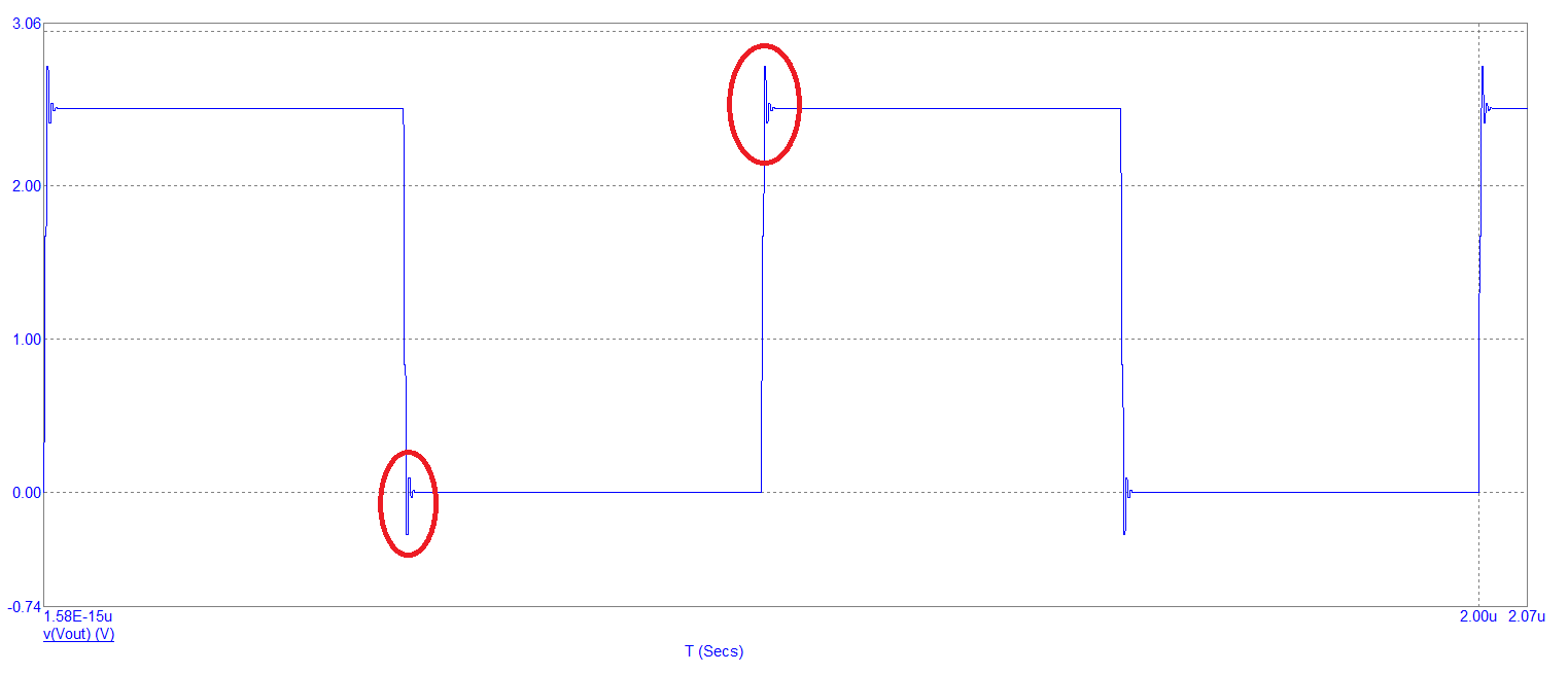
1 MHz output signal (Vout): -

enter image description here

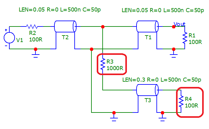
I don't think the edge disruptions are significant for RS-422 integrity. If you do something like this: -

enter image description here

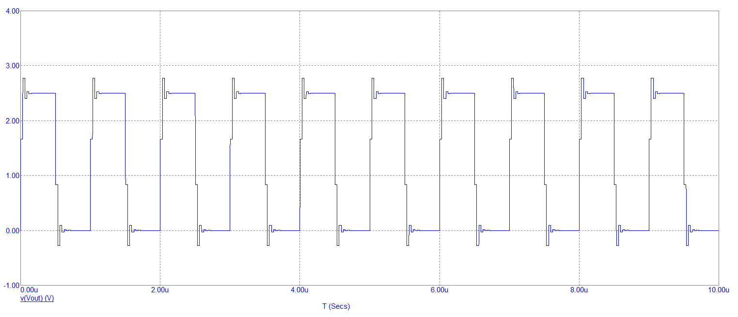
You'd be hard-pressed to see any degradation on your main RS-422 signal at all. And the monitor signal also looks good but, as expected is attenuated by 10:1.

Remember, my sims have used unbalanced signals and coax so, you'd need to split the 1 kΩ resistor into two 500 Ω resistors for proper RS-422.


As an afterthought...

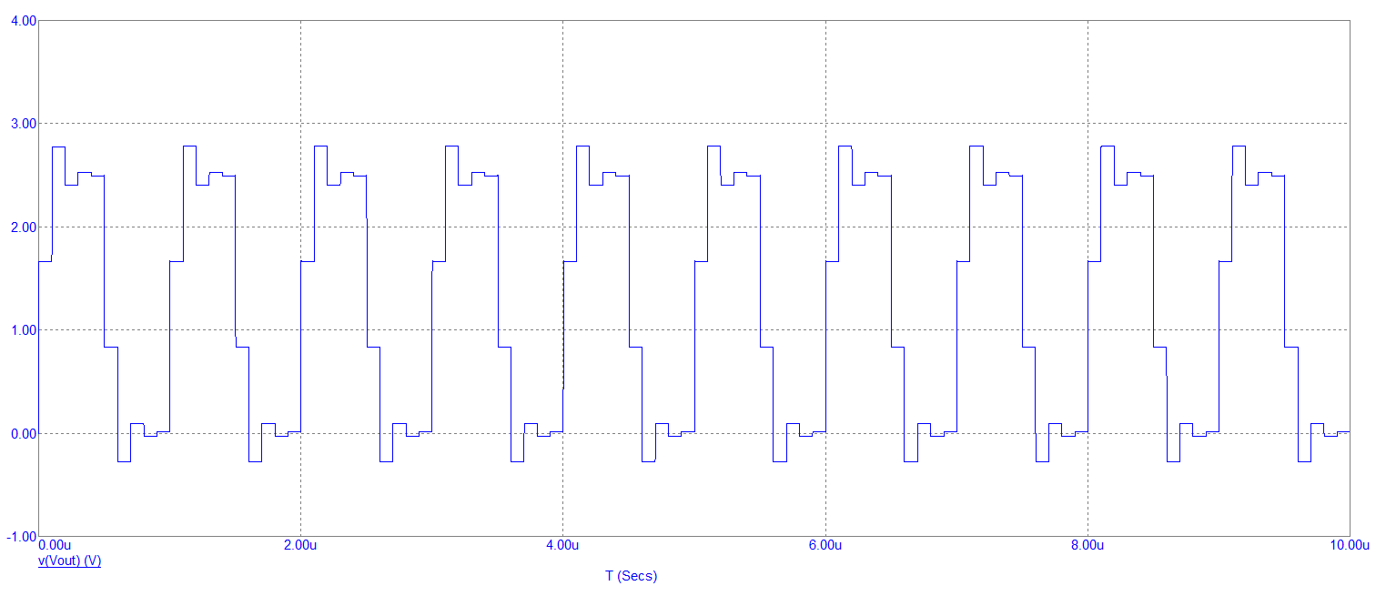
If I made the monitor line 3 metres long and didn't use any resistors, I'd see this disruption on the main signal: -

enter image description here

It's still OK and wouldn't throw up any significant corruptions.

If I made the monitor line 10 metres long, the main signal is starting to look crappy: -

enter image description here

\$\endgroup\$
1
  • \$\begingroup\$ Perfect Andy, as usual. Thanks a bunch, I'll add footprints for 500R resistors in each leg of the measurement stubs, as well as for 100R terminations - and put 0R shunts in the legs for now. Cheers! \$\endgroup\$ Commented Feb 7, 2021 at 16:10

Your Answer

By clicking “Post Your Answer”, you agree to our terms of service and acknowledge you have read our privacy policy.

Not the answer you're looking for? Browse other questions tagged or ask your own question.