1
\$\begingroup\$

enter image description here

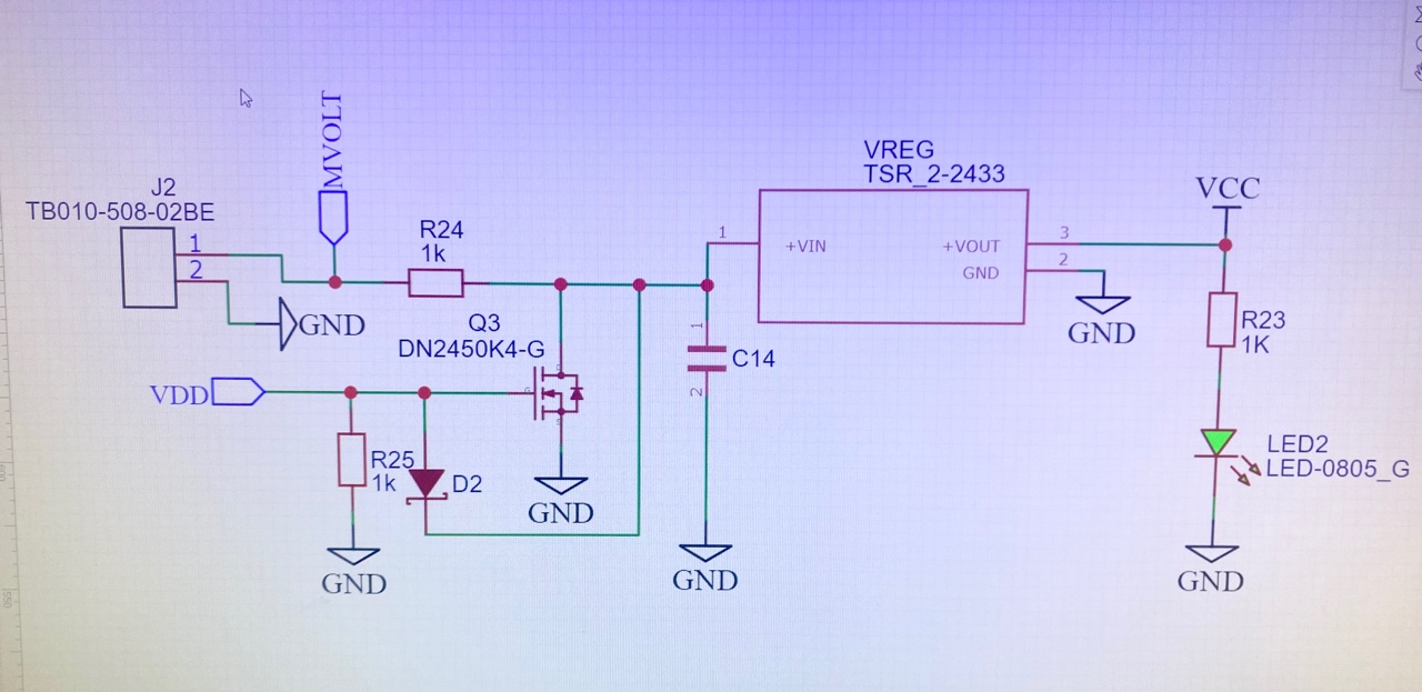
In my design the goal is to create a simple switch between power sources using a MOSFET.

  1. J2 is just a connector for the main power source which remains connected
  2. VDD is connected to a USB port
  3. VREG is a voltage regulator that requires the Capacitor there for switching applications. It takes in 5 -30 V in and outputs 3.3 V
  4. The LED should automatically light up if power flows through VREG that outputs 3.3 V
  5. The MOSFET used is DN2450K4, an N channel MOSFET

The goal is that the main power source is always connected but if I needed to program my overall device I would plug USB in and the MOSFET should cut/redirect the main power to ground and the USB should be powering the regulator.

When I tested this application with no main source attached and the USB connected to power the LED wasn’t lighting up, so I knew my VREG wasn’t receiving power. The MOSFET was slowly heating up though. Now my question is how can I change this circuit / MOSFET layout to better suite my application?

EDITED: I believe this application will work better and not create the original short hopefully I'm correct enter image description here

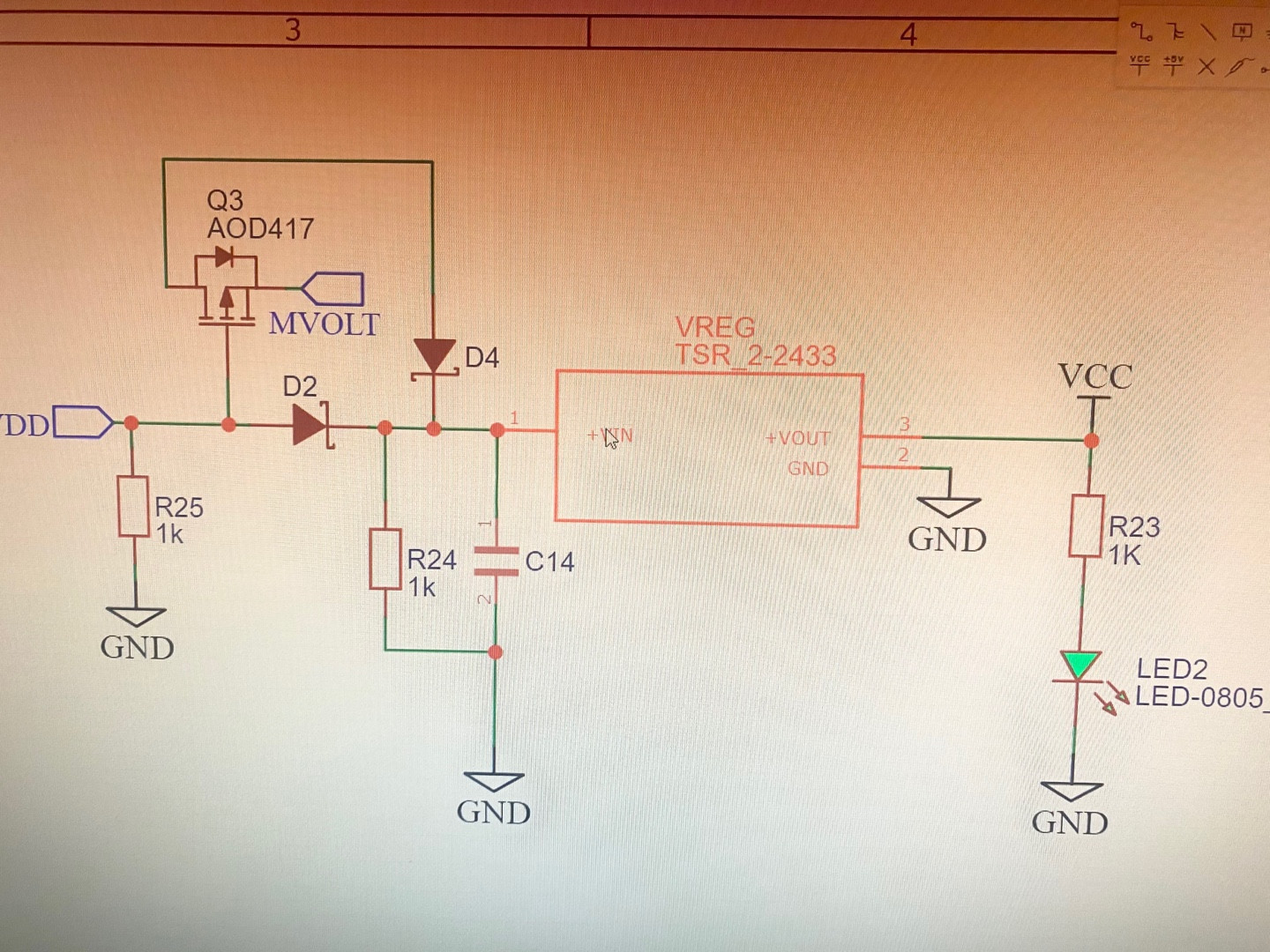
EDITED AGAIN: I changed MOSFETs. Now I'm using a P channel MOSFET AOD417 (DATASHEET) and switched some wires around based on the finds from this post HERE! I also added another diode D4 to block the charging possibilities of the USB (VDD) to the other source MVOLT

enter image description here

\$\endgroup\$
5
  • \$\begingroup\$ R24 won’t let much current flow. Maybe look at regulators that have an enable function \$\endgroup\$
    – Kartman
    Commented Mar 5, 2021 at 22:21
  • \$\begingroup\$ Look it in this way: At your home, do you turn off the light by making a short circuit ? \$\endgroup\$ Commented Mar 5, 2021 at 22:22
  • \$\begingroup\$ What is the purpose of D2? \$\endgroup\$
    – AnalogKid
    Commented Mar 5, 2021 at 22:33
  • \$\begingroup\$ @AnalogKid I think my placement of D2 is wrong its purpose was to stop current from flowing back to VDD but, I don't think its necessary as it has created a short. I will upload another image that I think works better. \$\endgroup\$
    – Randy
    Commented Mar 5, 2021 at 22:40
  • \$\begingroup\$ @MarkoBuršič thank you for pointing that out to me \$\endgroup\$
    – Randy
    Commented Mar 5, 2021 at 22:41

2 Answers 2

1
\$\begingroup\$

I believe this application will work better and not create the original short hopefully I'm correct
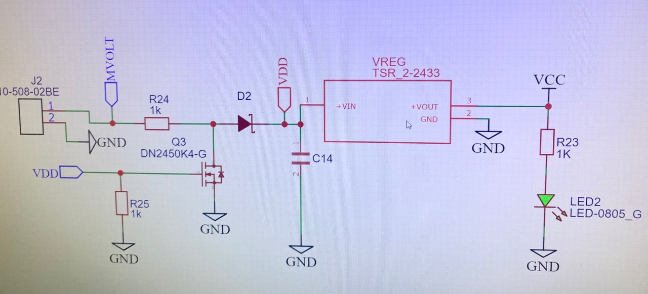
Nope. You still have the MOSFET creating a dead short between whatever is coming in through J2 and going through R24, to GND.

Separate from that, if you have an n-channel MOSFET with the source tied to GND, it cannot "switch between" anything. As a switch, all it can do is short something to GND.

Your goal still is not clear. If you want the presence of one power source to disconnect another power source, then you need a series switch in line with the source being disconnected, not a shunt switch. A p-channel MOSFET can do this. I did an image search for 'mosfet power switch schematic' (without quotes) and got lotsa examples.

\$\endgroup\$
1
  • \$\begingroup\$ THANK YOU those words, really helped put things into better perspective. I will conduct the same search as you and then I will update post accordingly after I fix the schematic \$\endgroup\$
    – Randy
    Commented Mar 5, 2021 at 23:20
0
\$\begingroup\$

In regards to your edited again schematic, the aod417 drain and source pins are swapped, drain should be at the MVOLT side. The pfet also acts as a reverse polarity protection, so D4 and R24 are not needed (unless D4 is a LED indicator?).

In addition the pfet will not work as a switch when MVolt is about greater than roughly 10Vs as Vgs will be too negative.

A helpful link for switching between power supplies, Switching between two power sources

\$\endgroup\$
1
  • \$\begingroup\$ thank you for the information, ill a look at the link you added and further my research and understanding of Vs and Vgs for MOSFETs so my next post will hopefully be a proper solution \$\endgroup\$
    – Randy
    Commented Mar 6, 2021 at 19:00

Your Answer

By clicking “Post Your Answer”, you agree to our terms of service and acknowledge you have read our privacy policy.

Not the answer you're looking for? Browse other questions tagged or ask your own question.