For an academic research project I need to visualise a fast movement. To do so, I need to sync a small (< 6 cm on the longest side) LED light source with the shutter of a high-FPS camera. The FPS are ~1000fps and the camera offers an 8-pin Hirose connector, of which two pins are described as flash output with optocoupler +/- in the technical datasheet. Space is very limited, so prefabricated solutions like standard flashes cannot be used. Unfortunately, I am inexperienced with LEDs and camera sync alike, so I'd be thankful if you could point me towards possible solutions to this problem.
-
2\$\begingroup\$ Show us the datasheet. \$\endgroup\$– HearthCommented Mar 24, 2021 at 14:17
-
2\$\begingroup\$ I did something similar for a 10 KHz line camera. To keep things simple I put a row of LEDs, each with a resistor and FET, then had the trigger out switch the FET. There are more elegant solutions, but this had low delay and very fast switching. Harder than then the electronics will be getting enough light. Test your LEDs with a short exposure time before you do anything. \$\endgroup\$– user1850479Commented Mar 24, 2021 at 14:34
-
1\$\begingroup\$ small LED light source - Small is relative. Small to me is an SMD LED? \$\endgroup\$– Mattman944Commented Mar 24, 2021 at 14:34
-
\$\begingroup\$ If the cost and risk are not an issue, standard flashes may be more appealing with the casing removed. If you contact a flash manufacturer they may even be willing to help you out since it increases rather than contracts their market share. \$\endgroup\$– K HCommented Mar 25, 2021 at 3:51
-
\$\begingroup\$ @Hearth the datasheet doesn't contain any further information on this, otherwise I would have shared it here. \$\endgroup\$– ddkkCommented Mar 25, 2021 at 12:09
1 Answer
Here is an educated guess as to how this output is intended to be used.
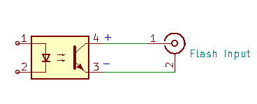
Your camera probably has an optocoupled transistor output. A normal photo flash is fired by pulling the pin signal down to the outer shell. Modern flashes have < 12V on the signal, so a photo transistor will work. Older flashes can have hundreds of volts on the pin, you must use a photo SCR/triac (available in higher voltages) to fire these.
Yours is most likely a photo transistor. When I fire my photo flashes with DIY setups, I use this circuit, similar to a camera output:
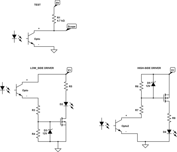
First, run a test to confirm the output circuit. The test circuit below will be unlikely to hurt anything. If you get the expected result, then move on to design an LED driver.
If the negative pulse width is acceptable, try the next paragraph. If not, you will need to shorten or stretch the pulse.
If you want to substitute an LED for the photo flash, the next two circuits are two options. I wouldn't use a V+ greater than 20V without adding another stage (unless you can find a spec for the camera opto output). The values will depend on your LED array characteristics. If V+ is 12V or less, you don't need the Zeners.
Be aware that LEDs when pulsed are no where near as bright as a Xenon flash. Also, if your LED bulb has a built-in power converter, you won't be able to pulse it.

simulate this circuit – Schematic created using CircuitLab

