2
\$\begingroup\$

I have this project to build an instrumentation system to measure the respiratory rate.

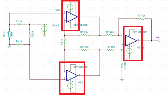
We decided to use a thermistor to measure the variation on the temperature of the air inhaled and exhaled. To measure the variation on the thermistor resistance we decided to use a Wheatsone bridge as shown below.

Since the variation was pretty small (the temperature varies between 25ºC and 28ºC) we needed to amplify the signal. For that we thought about using an instrumentation amplifier - INA128. However it wasn't available in the simulator we were using (which is TINA-TI) so we built the equivalent circuit.

I wanted to know if this is a good option to aquire and amplify this signal, and if this circuit is correct.

enter image description here

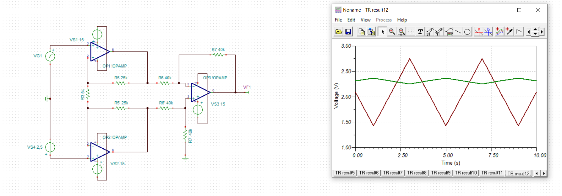
To be able to simulate the signal, we measured the signals on the points that were connected to the opamps, and used voltage sources with similar signals.

enter image description here

As you can see, the output has a DC component.

I wanted to know if there is something wrong with our Wheatstone bridge that could be causing that.

\$\endgroup\$

1 Answer 1

1
\$\begingroup\$

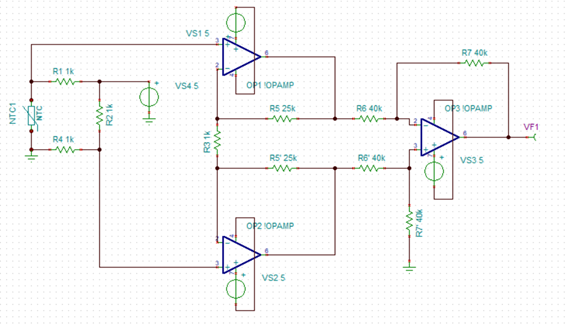
You should not apply power rails to op-amps like you have done: -

enter image description here

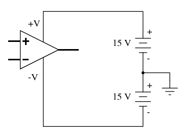
Each op-amp power pin needs a voltage relative to ground or 0 volts. So you apply a positive voltage to one power pin relative to 0 volts and a negative voltage on the other power pin relative to 0 volts. Like this: -

enter image description here

  • Also make sure that your op-amp model can work with voltages as low as those you are indicating.
  • Also make sure that your op-amp's input common mode range is sufficient for the power rail voltages you are using
  • Also ensure that the op-amp's output voltage range is adequate for the power rails you are using.
\$\endgroup\$
7
  • \$\begingroup\$ Thank you! I've corrected that. But regardind the rest of the circuit you think it is correct? \$\endgroup\$
    – Catarina
    Commented Apr 12, 2021 at 10:22
  • \$\begingroup\$ @Catarina does the simulation show it operates as you expected it to now? The circuit does look like a three op-amp configuration that acts like an InAmp if that's what you need to know. \$\endgroup\$
    – Andy aka
    Commented Apr 12, 2021 at 10:24
  • \$\begingroup\$ I think so. Its just that I was reluctant if the wheatstone configuration was indeed correct \$\endgroup\$
    – Catarina
    Commented Apr 12, 2021 at 10:25
  • \$\begingroup\$ It certainly looks like a correctly monitored wheatstone bridge. \$\endgroup\$
    – Andy aka
    Commented Apr 12, 2021 at 10:26
  • 1
    \$\begingroup\$ @Catarina the normal way is to apply an offset voltage into R7 so, where you have R7 connected to ground, connect it instead to a voltage source and adjust the voltage source until you get the desired output. \$\endgroup\$
    – Andy aka
    Commented Apr 12, 2021 at 10:32

Your Answer

By clicking “Post Your Answer”, you agree to our terms of service and acknowledge you have read our privacy policy.

Not the answer you're looking for? Browse other questions tagged or ask your own question.