1
\$\begingroup\$

I apologize in advance if this is a more common sense question - I'm still learning some of the basics and using this project partially to just build my knowledge.

Circuit Diagram

I've built this circuit with an input voltage of ~8V DC and a voltage across the capacitor of 251.7V. Parts used are...

IXFB110N60P3 MOSFET transistor - 600 Vds, 110 Ad

MSC050SDA070B Schottky Diode - 700 V, 50 A

DCP5P06100D200KS00 Capacitor - 1100 V, 100 uF

Clearly the circuit and all components work because of the successful voltage boost, but afterwards the MOSFET is shorted. I'm assuming that's due to the inductor sending current through after the power source is disconnected, but the large current rating is giving me some doubt. The capacitor still holds onto the voltage after power is disconnected, so I don't believe there is a current spike through the circuit due to that. I also make sure to discharge the capacitor after every use. What could be causing the MOSFET to short?

It should probably be noted that the only testing equipment I have access to is a standard multimeter. If additional information is required to answer, let me know but keep in mind that I am quite limited.

Thank you!

edit: forgot to include the inductor in my explanation. It is two inductors in parallel with one acting as a feedback coil for switching the MOSFET. Visually this looks like a coil around the original inductor.

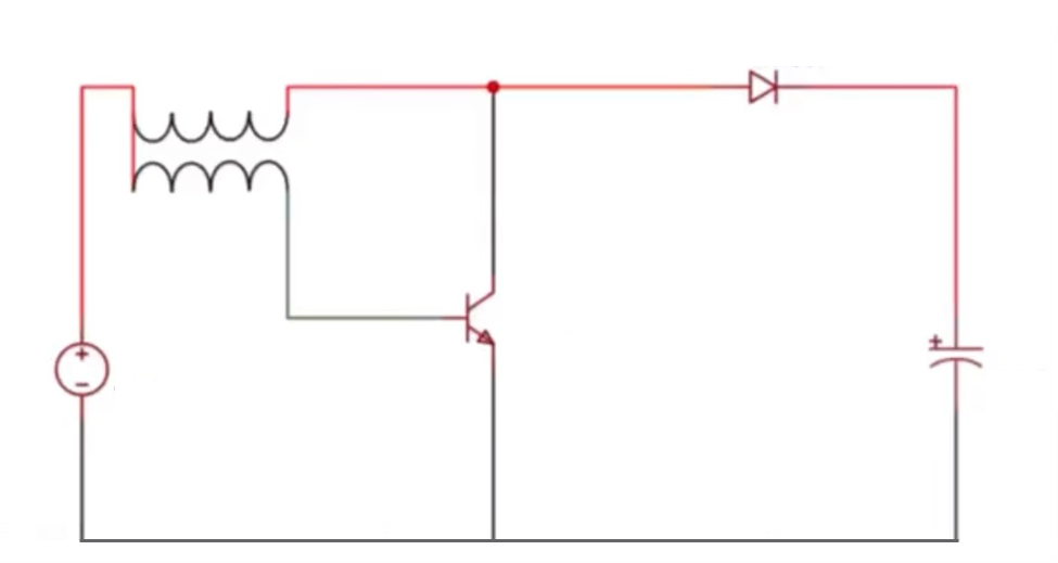
\$\endgroup\$
8
  • \$\begingroup\$ Welcome to EE.SE! Show Vce and Vge waveforms. \$\endgroup\$
    – winny
    Commented Apr 17, 2021 at 19:24
  • 1
    \$\begingroup\$ If you actually used a IXFB110N60P3, then the symbol you are using in your schematic is incorrect. The symbol in your schematic is for an NPN BJT. \$\endgroup\$ Commented Apr 17, 2021 at 19:29
  • \$\begingroup\$ Math Keeps Me Busy - thank you for pointing that out, and my apologies. Still learning :) \$\endgroup\$
    – tehwalrush
    Commented Apr 17, 2021 at 19:33
  • 1
    \$\begingroup\$ @tehwalrush You don't need a function generator, you need a oscilloscope. Without one it's hard to tell what exactly is happening. Possibilities are exceeding gate voltage and excessive power dissipation in the device. \$\endgroup\$ Commented Apr 17, 2021 at 19:46
  • 1
    \$\begingroup\$ You can’t troubleshoot a switch mode converter without an oscilloscope. \$\endgroup\$
    – winny
    Commented Apr 17, 2021 at 21:45

1 Answer 1

2
\$\begingroup\$

You have two coupled coils which you describe as "look[ing] like a coil around the original inductor". You need to understand that this is a transformer, and all the rules governing transformer behavior apply to it. As it "looks like a coil around the original inductor", it probably has a coupling ratio very close to 1. You describe the turns ratio as being 1:6, with the coil with fewer turns feeding the gate of your MOSFET.

You measured 251.7V across the capacitor. At some point the voltage across the primary was 251.7+0.7-8.0 = 244.4V. The voltage across the secondary was about 1/6 of that or 40V. The voltage at the gate of your MOSFET, at that moment was about 40+8=48V. That exceeded the allowable gate voltage of 40V (transient). Hence your MOSFET died.

\$\endgroup\$
4
  • \$\begingroup\$ The item not specified is not a transformer but two inductors in parallel, with one acting as a feedback coil for switching purposes. In real life this simply looks like coils around the original inductor. I use a 9V battery to power it all, and the voltage across it is ~8V. I will clarify all that in the post now, my apologies. \$\endgroup\$
    – tehwalrush
    Commented Apr 17, 2021 at 19:54
  • \$\begingroup\$ Do you know the coupling ratio and the turns ratio? \$\endgroup\$ Commented Apr 17, 2021 at 19:56
  • \$\begingroup\$ I don't think this is the right explanation. Using an IRF520 MOSFET, I was able to get over 140 volts from a 1.5V battery without it being shorted. By your calculations, this would mean 23.3V running through the secondary coil or 24.8 running through the gate - almost 5 more than its allowable gate voltage. \$\endgroup\$
    – tehwalrush
    Commented Apr 18, 2021 at 0:12
  • \$\begingroup\$ The IRF520 is rated for a max gate voltage of 20V, and indeed, 24.8V is almost 5V more. Just as 48V is 8V more than the 40V rating for the IXFB110N60P3. There is nothing strange about a transistor not failing until some point above it's rated voltage. The point is the manufacturer cannot reliably ensure that all (or even the majority) of its components will behave that way. So the max rating is not a guarantee that the part will be damaged at that voltage, but the end of the guarantee that it won't be damaged. But if you have a 6:1 turns ratio, the voltages must have been present. \$\endgroup\$ Commented Apr 18, 2021 at 0:51

Your Answer

By clicking “Post Your Answer”, you agree to our terms of service and acknowledge you have read our privacy policy.

Not the answer you're looking for? Browse other questions tagged or ask your own question.