1
\$\begingroup\$

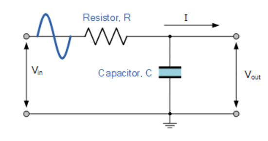
I am trying to calculate the Thevenin equivalent circuit of this low pass filter however, I have never done it with an AC input and am getting very confused.

$$R = 100\Omega ; C = 2\mu F$$

$$Vin = 2sin(2\pi*40*t) + 3sin(2\pi*142*t) + sin(2\pi*400*t)$$

enter image description here

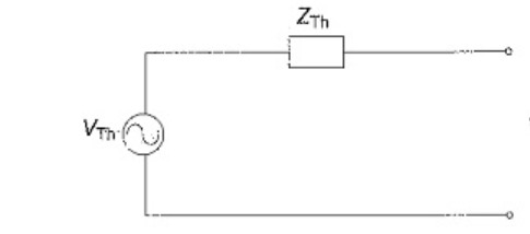
Where the Thevenin circuit looks like this:

enter image description here

To find Rth

To find Rth, I have short circuited the voltage source in order to find the equivalent resistance. The resistor R and the capacitor C are in parallel, therefore; $$Rth = R//C = \frac{R}{1+j\omega C}$$

Question: The Rth is in terms of w but the input signal has multiple frequencies, so how do I find the overall Rth?

To find Vth

I have found the transfer function which looks like this: $$\frac{Vout}{Vin} = \frac{1}{1+j\omega RC} = \frac{1}{1+j\omega 100*2*10^{-6}}$$

Question: How do I find the overall Vth when there are three separate sin signals?

\$\endgroup\$
6
  • 1
    \$\begingroup\$ This looks like a homework question. What does your instructor suggest? Please tell us why you want a Thevenin equivalent rather than just solving directly for the output voltage and current for a specific load? \$\endgroup\$ Commented Apr 18, 2021 at 14:41
  • \$\begingroup\$ @ElliotAlderson Nope, it is not a homework question... I want to calculate the Thevenin equivalent because I am going to introduce a load to the filter and I want to see how the circuit reacts but first I need a more simplified model. \$\endgroup\$
    – John
    Commented Apr 18, 2021 at 16:23
  • \$\begingroup\$ Why don't you just use superposition and calculate the response separately for each of the three frequencies? Why don't you just construct a simulaition in SPICE? \$\endgroup\$ Commented Apr 18, 2021 at 16:46
  • \$\begingroup\$ @ElliotAlderson oh sorry, I didn't know knowing how to do a Thevenin equivalent circuit is a secret. Apologies. \$\endgroup\$
    – John
    Commented Apr 18, 2021 at 17:21
  • \$\begingroup\$ Well, you show a figure that looks exactly like a circuit from a textbook. You don't tell us anything about how you actually want to use this circuit. The frequencies of interest appear to be arbitrarily chosen. Knowing how to construct a Thevenin equivalent is not a secret, and there are a wealth of resources available to you. But if you ask for a solution to a very specific and uncommon question...it quacks like a duck. \$\endgroup\$ Commented Apr 18, 2021 at 19:36

1 Answer 1

1
\$\begingroup\$

The Thevenin equivalent circuit will in general involve a frequency-dependent Thevenin Equivalent voltage source, and a frequency-dependent impedance in series with the source. You can evaluate the output at any given frequency.

You have not done your calculation correctly so far. Start by finding the Thevenin equivalent source voltage by calculating the open-circuit output voltage, which is equal to the Thevenin Equivalent voltage source \$V_{th}\$:

$$V_{th} = \frac{V_{in}}{(1+j\omega RC)}$$

Next you can calculate the Thevenin Equivalent impedance \$Z_{th}\$ by calculating the short-circuit current \$I_{ss}\$and setting that equal to \$V_{th}/Z_{th}\$:

$$I_{ss} = \frac{V_{in}}{R} = \frac{V_{th}}{Z_{th}}$$ $$Z_{th} = \frac{V_{th}}{V_{in}/R} = \frac{R}{1+j\omega RC}$$

So now you have your Thevenin Equivalent voltage source and impedance. You can now calculate the output at any given frequency by inserting your load impedance \$Z_L\$ in series with the Thevenin impedance and calculate the output using a voltage divider (which I assume was your plan all along).

Now, this is true at each given frequency. So to get your time response, you should use superposition and calculate the response to each frequency separately, and then simply sum them.

Note: to calculate the response to a sine wave input, you should decompose the sine wave into its positive and negative frequency exponentials, calculate the response to each, and sum them back.

\$\endgroup\$
4
  • \$\begingroup\$ Thank you very much, I appreciate it! Was stuck on this for days! \$\endgroup\$
    – John
    Commented Apr 18, 2021 at 20:01
  • \$\begingroup\$ I don't get how this is the Thevenin equivalent of the circuit. I am assuming you are looking at the circuit from the Vout terminals. In the actual circuit, Vout is taken across the capacitor, whereas in the Thevenin equivalent circuit it is taken across both the capacitor and resistor. \$\endgroup\$
    – Wais Kamal
    Commented Apr 18, 2021 at 22:09
  • \$\begingroup\$ @WaisKamal Remember that in the Thevenin Equivalent representation, the original resistor and cap are not there anymore. Just an equivalent voltage source and an equivalent impedance in series with it. The load is connected in series with them. \$\endgroup\$
    – rpm2718
    Commented Apr 18, 2021 at 23:03
  • \$\begingroup\$ And also, just an additional comment — this circuit can easily be analyzed without using Thevenin. That is just how the OP was interested in approaching it, and it is a useful exercise to do so. \$\endgroup\$
    – rpm2718
    Commented Apr 18, 2021 at 23:05

Your Answer

By clicking “Post Your Answer”, you agree to our terms of service and acknowledge you have read our privacy policy.

Not the answer you're looking for? Browse other questions tagged or ask your own question.