0
\$\begingroup\$

This is a follow up to my previous question: For my Amazon Echo related project, I realized that the speakers in the Echo are being driven from a differential amplifier, and not a single ended one.

What I'm trying to do is sample audio from the tweeter and subwoofer speakers into the ESP32 microcontroller for a music reactive LED project. The reason why I believe I need to convert the signal to a single ended one is because the signal needs to be referenced to GND so the ADC on the ESP32 will be able to read the signal properly.

Any help or additional info would be great.

\$\endgroup\$

2 Answers 2

1
\$\begingroup\$

Simply use the signal from one speaker wire. If the amplifier has a single supply polarity then this signal will already have some DC on it (half the supply voltage) and it will never go below 0VDC.

\$\endgroup\$
1
  • \$\begingroup\$ Likely the simplest answer, and may work. However, it's not very flexible and has some drawbacks. Both the signal amplitude and DC average need to be appropriate for the ADC input, and this approach has no way to alter them. Also, it will have relatively low noise immunity -- supply noise can translate to common-mode noise on the diff amp output, but using only one input sums this noise directly with the signal instead of rejecting it by taking the difference. One might also need to address the issue of asymmetric loading of the amp output (dummy load on other output). \$\endgroup\$ Commented Apr 25, 2021 at 2:14
1
\$\begingroup\$

Ideally, you want to make use of the use of the entire ADC input range, which maximizes the dynamic range of your digital output. To do so, you will need to do two things:

  1. Level shift the single-ended signal so that its average value is at the mid-point of the ADC full scale range, or Vfs/2.
  2. Alter the gain of the signal so that the peak-peak value is slightly less than the full-scale ADC voltage, Vfs. (Why slightly less? To ensure that there is no saturation, which will cause nonlinearity, and is unacceptable for audio applications.)

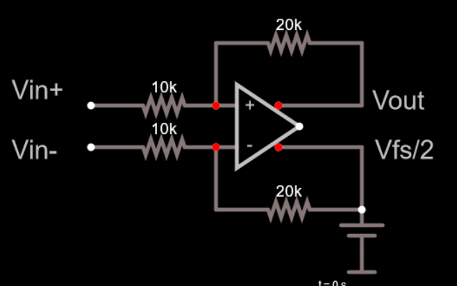
A representative circuit to accomplish this is a fully differential opamp with resistive feedback.

enter image description here

The gain is set by the ratio of the feedback to input resistors (here, the gain is shown as 2), and the output offset is set by a low-impedance reference of Vfs/2. You may need to compensate the loop.

\$\endgroup\$

Your Answer

By clicking “Post Your Answer”, you agree to our terms of service and acknowledge you have read our privacy policy.

Not the answer you're looking for? Browse other questions tagged or ask your own question.