2
\$\begingroup\$

Today, I've tried powering an 8520 coreless brushed 3-5V 0.15A DC motor from a 5V/1A power bank. The powerbank is unfortunately unspecified (its old and was originally a part of a company gift bag, so no receipt or model number, anything).

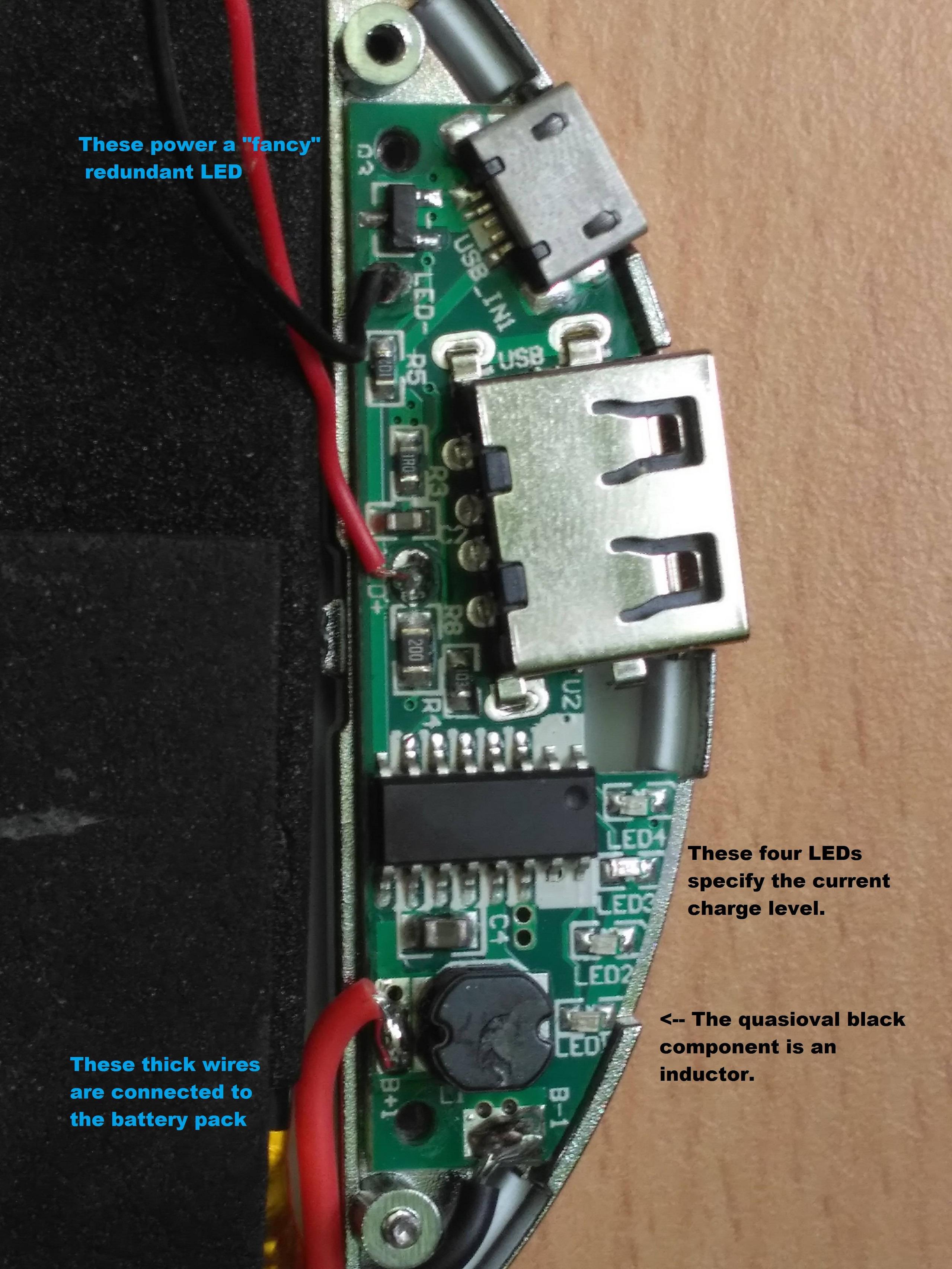
This is the PB's power management chip: power management chip
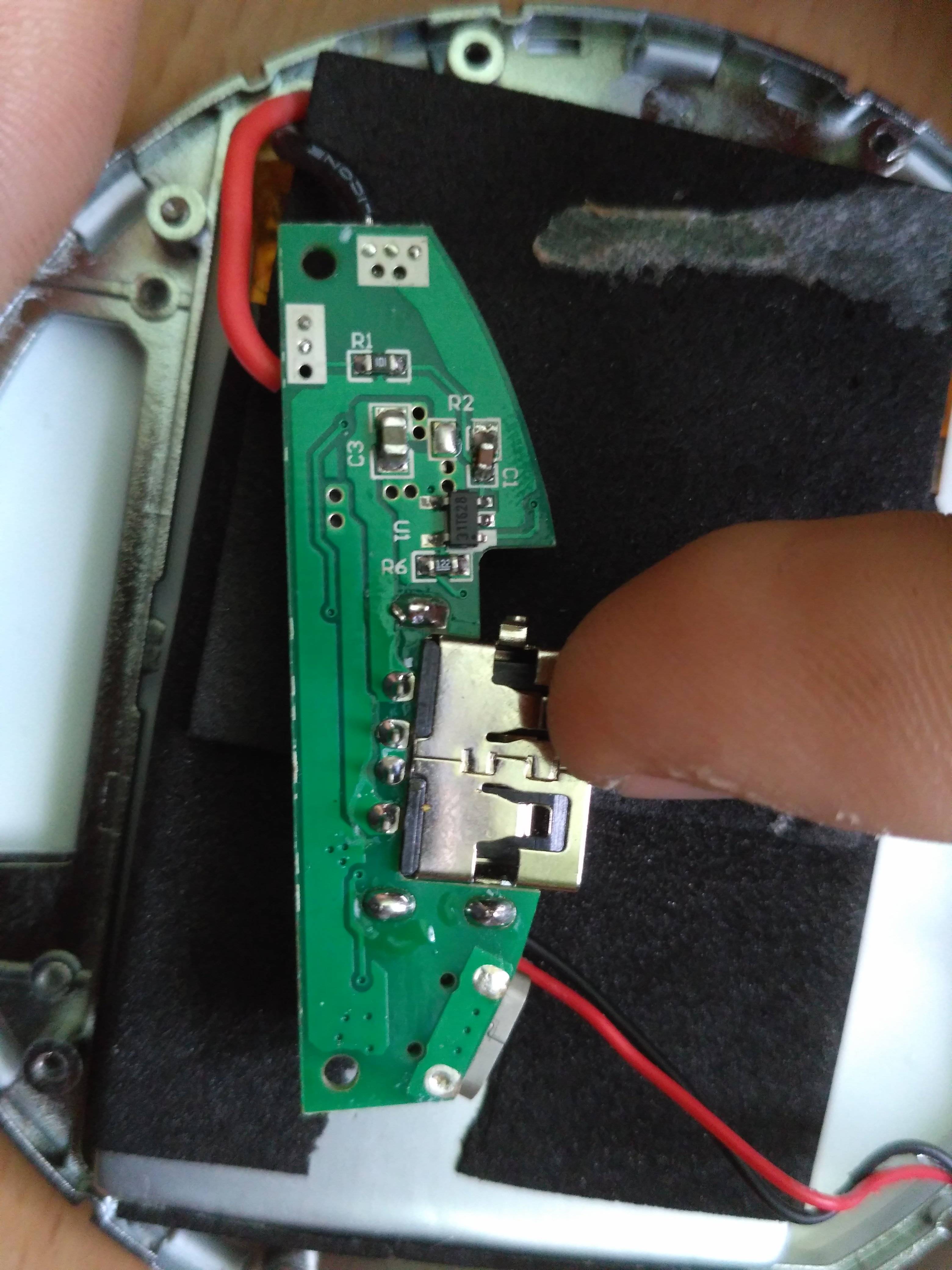
This is the bottom view of the same chip: bottom view of power man. chip
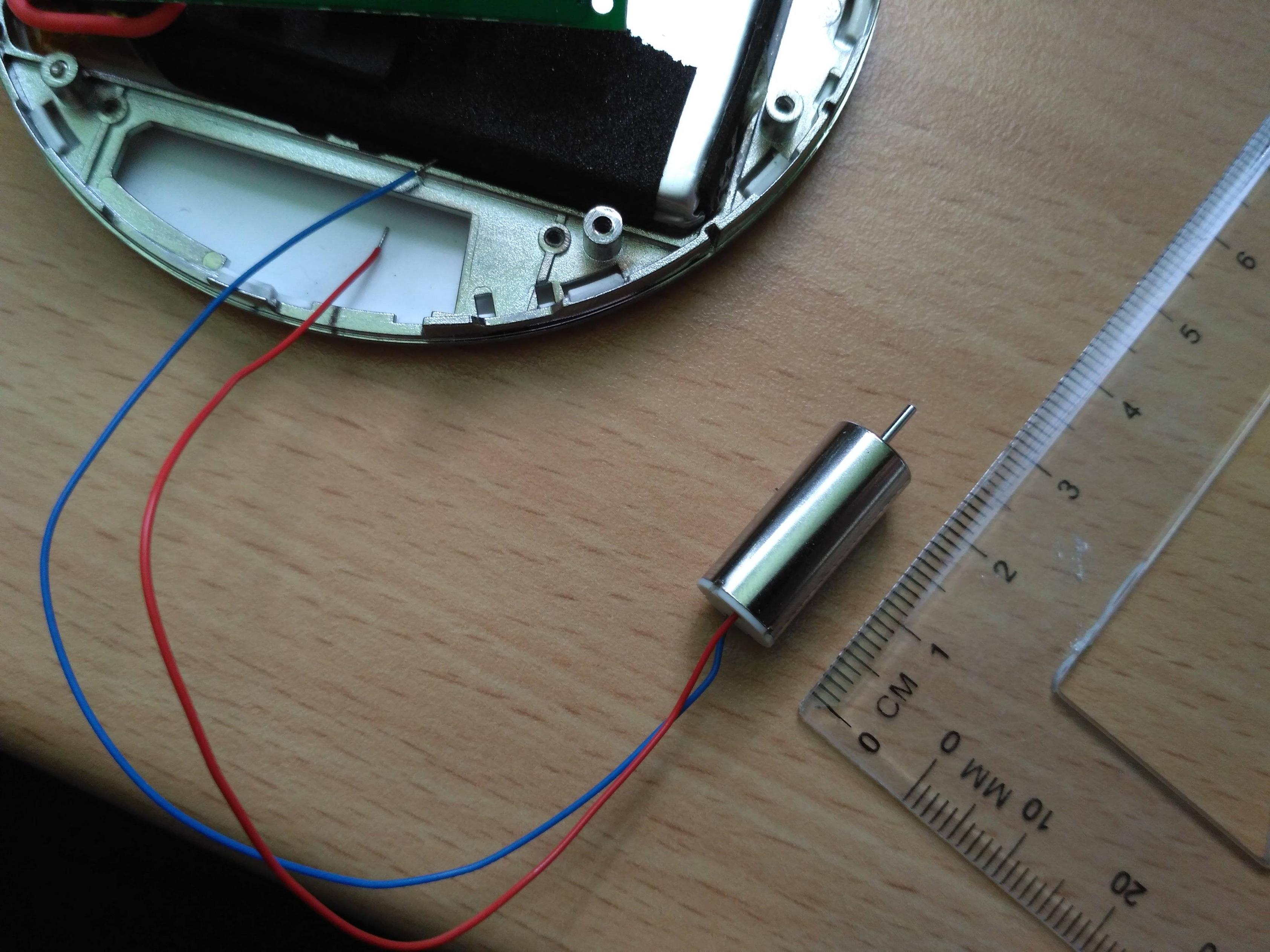
This here is the motor in question: brushed DC motor

And this is how I connected the motor to the PB (I've tried both polarity directions). motor to powerbank
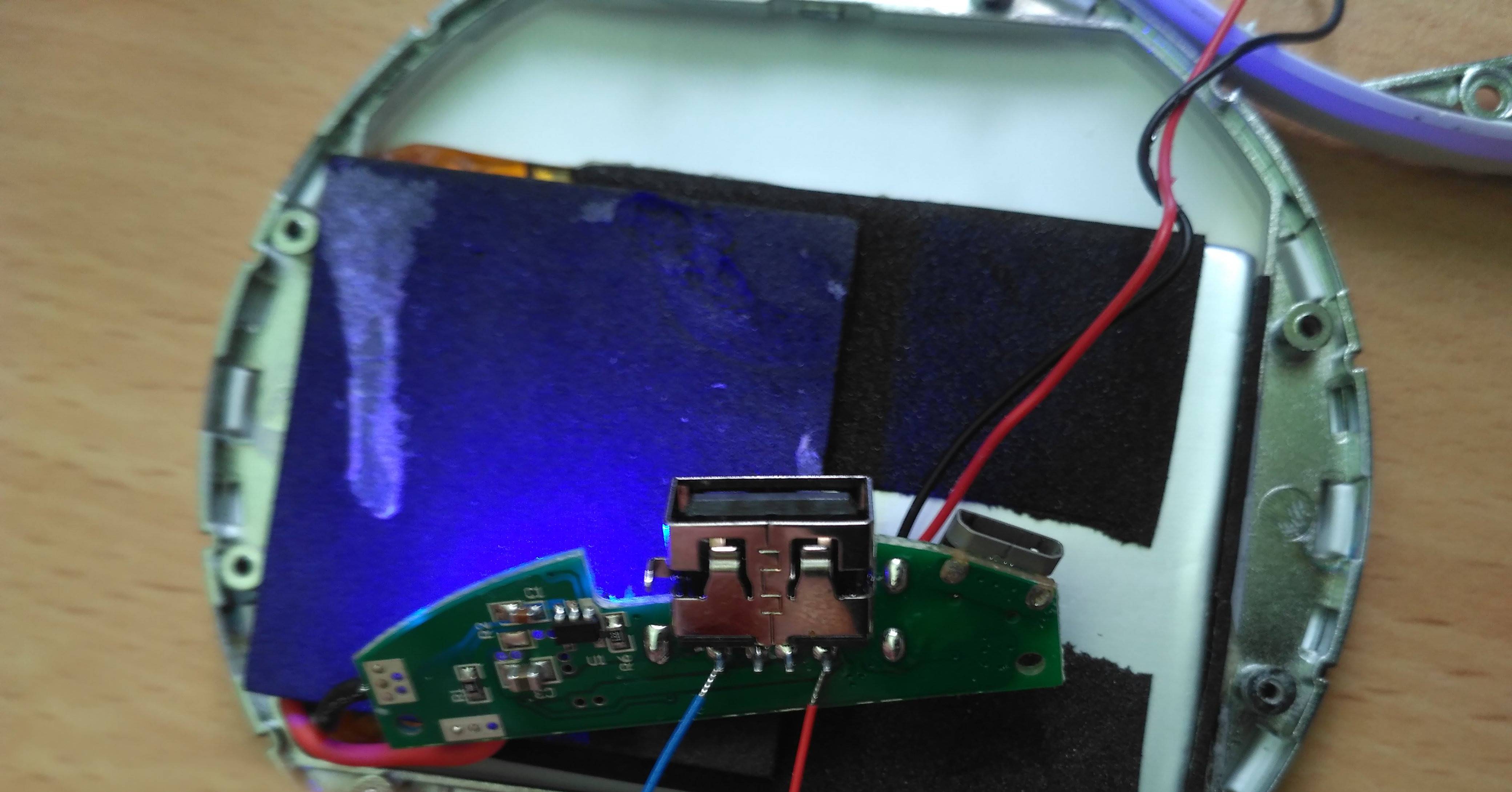
The blue light indicates that the PB is on. I suspect a part of the circuitry checks whether the PB is completing a circuit and only then turns on the PB (no idea how that might work). When I short those two USB contacts with my finger, the blue light turns on for cca. 10 seconds and then turns off. When I connect a DC voltmeter, it shows 5V, as advertised, and the blue light stays on for cca. 10 more seconds after the circuit is broken, exactly the same as with my finger. When I connect the motor, however, it spins for a fraction of a second (jerks, more likely) and then immediately stops. The blue light turns off immediately as well.

I've tested the resistance of the motor at standstill and it turns out to be around 0.8 Ohms. The PB is nearly fully charged (very recently charged & corresponding to the LED charge-information lights, which are all on).

I possess a very, very surface-level knowledge about brushed DC motors (and electronics in general), so I've come here for advice. Could this be caused by some sort of mechanism protecting the batteries from a reverted voltage (such as the back electromotive force generated by the motor)? I've also tried connecting a smaller, similar motor (including a propeller, salvaged from an old RC plane, I have no information about it though except its visual properties), and it spun without issues (it has 6.2 Ohms at standstill). Maybe the missing core has something to do with it? Anyway, I'm at a loss. Can anyone give me any hints about what could be going wrong? Thank you very much.

EDIT: I've tested the motor on a cellphone 3.7V battery (no controller) and it runs fine. Keeps going until I break the circuit.

\$\endgroup\$
15
  • 1
    \$\begingroup\$ "I've tested the resistance of the motor at standstill and it turns out to be around 1200 Ohms" That's the problem. It should be more like 1 ohm. If you're lucky, spinning it with a Dremel or something will clean the brushes. Or it may be toast. \$\endgroup\$
    – user16324
    Commented May 5, 2021 at 13:14
  • \$\begingroup\$ @user_1818839 My bad! Apparently, I cannot read multimeter values as well. I've refreshed my DMM knowledge and confirmed that, actually, the resistance of the motor unpowerable by my PB is at 0.8 Ohms instead. The reason why is 0.8 not 1200 divided by a power of 10 is the fact that my original multimeter was miscallibrated. I've also added some additional information. \$\endgroup\$ Commented May 5, 2021 at 14:44
  • 1
    \$\begingroup\$ Good work. Now calculate the starting current from \$ I = \frac V R \$ and see if you PSU is capable. \$\endgroup\$
    – Transistor
    Commented May 5, 2021 at 14:48
  • \$\begingroup\$ @Transistor I haven't managed to properly measure the true current flowing through the motor during startup, as my largest amperemeter scale is 500 mA; I've confirmed the current is larger, which corresponds to the expected current of $\sim 6A$. The motor listing however claimed the operating current is 0.15A! Does it mean the current draw drops significantly when the motor is running? My PSU should not be capable of delivering this much current when used as a powerbank, but connecting the motor directly to the battery inside lets the motor spin correctly. \$\endgroup\$ Commented May 5, 2021 at 15:17
  • 2
    \$\begingroup\$ The startup current can be up to 10 times the running current. Connecting directly to the battery bypasses the current limiting circuitry and all the battery protection! \$\endgroup\$
    – Transistor
    Commented May 5, 2021 at 15:18

2 Answers 2

1
\$\begingroup\$

Sometimes the USB port is enabled to deliver the 5 V voltage by a correct biasing of the d+ and d- contacts. Try to connect a cellular phone to the USB port and let your motor soldered to the pc board as in your last photo. It should spin correctly.

\$\endgroup\$
1
  • \$\begingroup\$ I've tried this, and unfortunately it does not work. I didn't solder the motors to those contacts, however - I believe it would make no difference. I have been practicing the holding the motor cables steadily enough technique these past few days. \$\endgroup\$ Commented May 5, 2021 at 22:20
0
\$\begingroup\$

I was experiencing the exact same problem this afternoon, I managed to fix it by adding a diode to the circuit

\$\endgroup\$

Your Answer

By clicking “Post Your Answer”, you agree to our terms of service and acknowledge you have read our privacy policy.

Not the answer you're looking for? Browse other questions tagged or ask your own question.