2
\$\begingroup\$

I am trying to design a circuit, which will drive my home valves which is on 24V and by specifications must supply 2A ( but this is quite suspicious, and probably it is requiring much lower current, but sill I wish to make it fulfill this requirement ). I found a few circuits, but when I doublechecked them - most of them ends with an issue. So, just as a precaution I wish to ask peoples which done this eventually for guide.

  • How to drive IRF520 with ESP32 3.3V output correctly ?
\$\endgroup\$
3
  • 2
    \$\begingroup\$ Is the application using the IRF520 FET as a simple on/off switch, or do you need to PWM control it? And if you need PWM at what frequency? If it's just an on/off you could use a smaller logic level controllable FET to control the gate voltage of the IRF520. Perhaps with a resistor divider on your 24V rail to maintain Vgs < 20V. \$\endgroup\$
    – gcr
    Commented May 6, 2021 at 15:41
  • \$\begingroup\$ Nope, no PWM. Just simple switching on/off the solenoid. \$\endgroup\$ Commented May 6, 2021 at 15:44
  • \$\begingroup\$ I've moved the topic here, after the practitioners in the discussion pointed me more toward the right question: electronics.stackexchange.com/questions/563848/… \$\endgroup\$ Commented May 6, 2021 at 18:06

1 Answer 1

2
\$\begingroup\$

In my experience with 24V solenoid valves, they don't need the maximum listed current. For a 2A solenoid it probably needs 1-1.5A to activate, and then ~500mA to hold open. You can design circuits which supply this.

The listed mosfet has a threshold voltage between 2 and 4 volts, so it's likely the ESP32 can't turn it on from 3.3V. You would want a smaller mosfet to drive the gate on it.

This is a really obnoxious part to design this circuit with, because the gate voltage range is above a microcontroller but it's also below 24v. I would encourage you to get a logic level mosfet if you have the option to. That way you don't need to worry about all of these gate voltage thresholds, and you could use 1 mosfet and 1 resistor.

This is the best I could come up with, it should be compatible with most garden variety p-mosfets and n-mosfets, and a handful of 10k resistors:
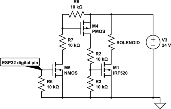
schematic

simulate this circuit – Schematic created using CircuitLab

EDIT:

This is how it would simplify with a logic-level mosfet.
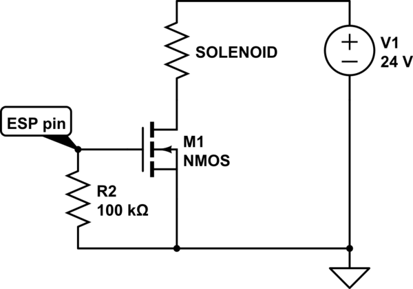
schematic

simulate this circuit

Very easy to find a new part with:

  • VDS of greater than 24V, 30 is very common
  • Current rating greater than 2A
  • low RDSon specified between 1.8-4.5V, usually means its logic level
  • VGSth max of 3.3V or less
  • low input capacitance, otherwise put a series resistor
\$\endgroup\$
12
  • 1
    \$\begingroup\$ If OP is able to adjust the program on the microcontroller, couldn't they invert the output (pull output pin low to energize solenoid) and omit M5, R6 & R7? \$\endgroup\$
    – Theodore
    Commented May 6, 2021 at 17:43
  • 2
    \$\begingroup\$ @Theodore I don't believe so, the pin would need to be tolerant of 24v if it's in open drain due to R5. If that was the case you could high-side switch the solenoid with M4 & R5 directly and omit everything else \$\endgroup\$
    – zozwold
    Commented May 6, 2021 at 17:50
  • 1
    \$\begingroup\$ I will edit the answer to show how it simplifies if you choose a different mosfet \$\endgroup\$
    – zozwold
    Commented May 6, 2021 at 17:54
  • 1
    \$\begingroup\$ @zozwold ...of course you're right... it would have to be M1 that's omitted and M4 would have to be a power PMOS high-side. \$\endgroup\$
    – Theodore
    Commented May 6, 2021 at 17:55
  • 1
    \$\begingroup\$ Maybe it is the best to accept this answer, and post another question. So more peoples will benefit from both ? \$\endgroup\$ Commented May 6, 2021 at 17:55

Your Answer

By clicking “Post Your Answer”, you agree to our terms of service and acknowledge you have read our privacy policy.

Not the answer you're looking for? Browse other questions tagged or ask your own question.