2
\$\begingroup\$

I am building a solar pool heater using a solar panel to power bilge pumps that push water through irrigation pipes. When there's enough sun to get the panels to its typical voltage (~21.6V 6.16A) but not enough to provide enough current for the pump, then the relay cuts on and off rapidly until I turn down the potentiometer to a trickle. I'm just learning about electronics and have a basic understanding of the components, of which I assume I'm missing something important here.

I've currently wired this as:

schematic

simulate this circuit – Schematic created using CircuitLab

Solar Panel -> Relay with cutoff at 10V -> Buck Converter to 12V -> Potentiometer -> 12V 2.5Amp Bilge Pump

Do I need to add a battery or a capacitor somewhere to ensure the relay has enough power to stay on or remain off when there isn't enough power overall? Is there a way to reserve enough current to power the relay and buck converter?

Thank you!

Actual components in use are:

\$\endgroup\$
5
  • \$\begingroup\$ Provided that buying from Amazon and the like is not the best to get complete datasheets, I understand the saving of time. Could you explain why you use the relay? What you want to protect? the panels provide 12V, maybe you use 2 in series (and thus your statement on 23V). The buck converter will feed the pump at the correct 12V voltage. What is the real current absorption of the pump (officially 2A)? I think that even at reduced sunlight panels will provide enough current (5.5A I assume at max insolation). \$\endgroup\$
    – andrea
    Commented May 9, 2021 at 14:06
  • \$\begingroup\$ A warm welcome to the site. Please edit your question and add a drawn schematic. The schematic tool seen when you edit your question is a breeze to use. The better the quality of your question, the better the quality of the answers it will attract. Again, welcome. \$\endgroup\$
    – TonyM
    Commented May 9, 2021 at 14:32
  • \$\begingroup\$ @andrea I followed a youtube video, and it's clear in retrospect they didn't know what they were doing :) The Amazon description says 100W 12V, but the panel itself says something 23V at 5-6amps (it's outside and I can add more exact numbers soon) on the back. The buck converter reports a draw of ~1.91 amps at 12V when the pump is running at 100% (potentiometer fully turned). The person on the youtube video seemed to intend for the relay to shut power off when the sun drops, rather than providing a continuous trickle. I'm treating this project firstmost as a learning experience. \$\endgroup\$ Commented May 9, 2021 at 14:42
  • \$\begingroup\$ @TonyM thanks for the warm welcome! I've never done such a schematic before, so I made my best attempt at it. I couldn't find anything resembling a DC motor, and I didn't know how to represent the component values properly. Feedback from anyone also appreciated if you have the time! \$\endgroup\$ Commented May 9, 2021 at 14:59
  • \$\begingroup\$ I am voting to close this because the schematic is inadequate for diagnosing the problem. Details and clarity needed. Unless closed, community bot may keep bumping it up. \$\endgroup\$ Commented May 4 at 23:40

3 Answers 3

1
\$\begingroup\$

Do I need to add a battery or a capacitor somewhere to ensure the relay has enough power to stay on or remain off when there isn't enough power overall? Is there a way to reserve enough current to power the relay and buck converter?

Short answer: the simplest solution is to (1) add a battery, (2) add a battery charging controller, (3) remove the "10V switch", and then wire the system such that:

  1. the solar panel charges the battery through the battery charge controller.
  2. the battery supplies the buck converter via the "relay" you already have.

The rest of the wiring is as you have shown it.

Battery Selection
You may be tempted to use a lithium battery, but I would recommend starting with a sealed lead-acid battery ("SLA"), rather than a Lithium battery, for the following reasons:

  1. lower cost, wider choice, commonly available.
  2. lower risk of fire/explosion.
  3. more robust against physical and electrical stress.
  4. more robust against high temperatures.

Once you have gained some experience with SLA, then perhaps consider lithium batteries later, and see if the benefits outweigh the costs and hazards.

Battery sizing: if I understand your application, it seems you don't need the pump to operate independently of solar power for long periods; perhaps a 30-minute run time at full power is more than enough. The pump datasheet says that the maximum current draw is 2A at 12V, so that means a 1A-hr battery would be sufficient. The smallest battery I found on Amazon was 4A-hr, there were several options of 7A-hr, here are a couple of examples:
https://www.amazon.com/dp/B09V4GVNYQ/ref=syn_sd_onsite_desktop_0?th=1

https://www.amazon.com/ML7-12-Battery-Mighty-Brand-Product/dp/B00K8V30D0/?th=1

Battery Discharge Protection
The "relay" you listed: more accurately, this is a Low Voltage Protector Disconnect Switch, which is intended to protect a battery from being excessively discharged. It does this by disconnecting the load from the battery to prevent further discharge when the battery voltage falls below a user-programmed threshold. It is not intended to serve as a battery charging controller.

Battery Charger Controller
The solar panel you listed: this does not include a "controller" which is the word used to indicate a "battery charging controller". I suggest you select a suitable battery charging controller recommended by the vendor of the battery you choose, since the controller should be chosen to suit the battery, rather than the solar panel. Of course, yes, the solar panel should suit the charge controller also, but the primary concern is to ensure the battery is correctly charged and is protected from over-charging, and over-discharging. Here are a couple of controller options to consider:
https://www.amazon.com/Controller-Intelligent-Regulator-Paremeter-Adjustable/dp/B08L8TBCK6/?th=1

https://www.amazon.com/Controller-Intelligent-Regulator-Paremeter-Adjustable/dp/B0C9LHNGX2?th=1

The other option is to replace the solar panel with one that includes the battery charger controller, here is one option that may be suitable:-

https://www.amazon.com/dp/B079JVBVL3?th=1

Battery Ripple Current Filter
The buck converter you listed: the datasheet for this is not clear about how well the input current is filtered. Input current to a buck converter can be very "chopped", which may cause electrical interference, and may also damage the battery. I recommend placing a "pi" filter (also known as a "C-L-C filter") between the battery and the buck converter input, placed close to the input of the buck converter. Here is the schematic of this filter:
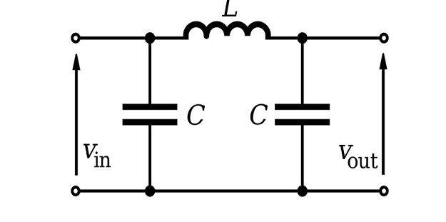
enter image description here source: https://diyguru.org/term/what-is-a-pi-filter/

I have not been able to find a suitable C-L-C filter on Amazon. But you can get the components (inductors and capacitors) quite easily, and these are very easy to assemble (with a soldering iron and some wire). The trick is how to select the components - perhaps that is a topic to discuss in a separate question/answer.

Of course, all of these product suggestions are suggestions only, please do your own due diligence to ensure they are suitable for your application:

\$\endgroup\$
3
  • \$\begingroup\$ Does this post answer the question of why the "Relay [is] Switching On and Off Rapidly During High Current Draw"? Or is it just giving general advice for how to set up a PV system? \$\endgroup\$ Commented May 5 at 3:08
  • \$\begingroup\$ @MathKeepsMeBusy It answers the question "Do I need to add a battery or a capacitor somewhere". To answer the question "Why the relay is switching rapidly" requires a better understanding of the system components, which requires data which is not provided by the vendors of said components. \$\endgroup\$ Commented May 5 at 3:14
  • \$\begingroup\$ @MathKeepsMeBusy Cont'd: Of course, I can speculate that the most likely cause is due to the buck converter pulling heavy current during pump startup, causing the "relay" to drop out momentarily, which then recloses once the current falls, and the cycle then repeats until the pump manages to finally get to full speed, but to get a definite diagnosis requires test equipment and skilled operator of same, or comprehensive datasheets, neither of which seem to be available to the OP. \$\endgroup\$ Commented May 5 at 3:15
0
\$\begingroup\$

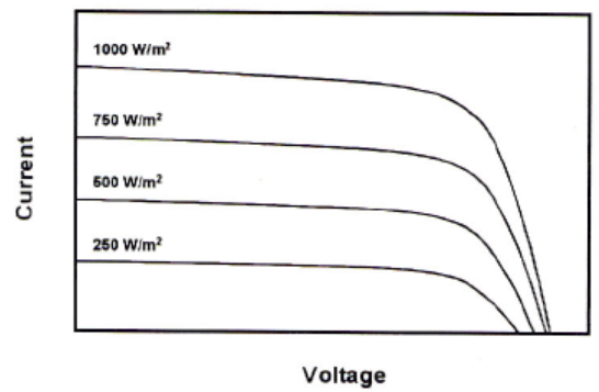
First point. A solar cell is like a pn diode basically a current source up to a given voltage, above which the current reduces. When solar irradiance reduces, the I-V curve lowers. Please, have a look at a past discussion: How to estimate solar panel output as a function of solar radiation I show the relevant image below. enter image description here

Second point. The minimum voltage relay is proposed to avoid excessive discharging of batteries, to avoid to reduce the expected life. For the PV panels we do not have these problems. When sunlight is off they will not provide any current. I am not aware of any wearing due to low irradiance. Commonly used panels on roofs and PV parks are not switched off, but converters downstream are not operated for a matter of efficiency and economy.

Conclusion. You can remove the "relay" from your scheme and see how things are going. The pump will not suffer of working at lower voltage and overheat because the converter guarantees the feeding voltage.

Remark. The relay would have been a good idea if there is some kind of hysteresis. It was conceived for batteries, thinking of a constant discharge towards lower values. In your case you might have an increase of irradiance at dusk for some time, and also cause by moving clouds. By the way even the buck converter will have a min input voltage, and will go off below that.

\$\endgroup\$
0
\$\begingroup\$

I posted an answer previously that involved adding a battery, but have since discovered what may be a very simple solution to the problem of "the relay cuts on and off rapidly until I turn down the potentiometer to a trickle."

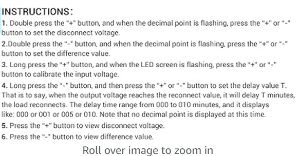
Simply increase the turn-on delay time of the "relay". Set this to something like, say, 1 minute. Here is a screenshot from the Amazon link you provided:

enter image description here

And refer to note 4 of this screenshot:
enter image description here

Expected Operation
If there is not enough solar power to start the motor, the relay will disconnect the buck converter and will then wait before attempting another start. It will continue to do this every minute until either (a) the pump starts, or (b) the voltage from the solar panel is too low to power the relay itself.

The "relay" you listed:
More accurately, this is a Low Voltage Protector Disconnect Switch, which is intended to protect a battery from being excessively discharged. It does this by disconnecting the load from the battery to prevent further discharge when the battery voltage falls below a user-programmed threshold. It is not intended to serve as a battery charging controller.

\$\endgroup\$

Not the answer you're looking for? Browse other questions tagged or ask your own question.