3
\$\begingroup\$

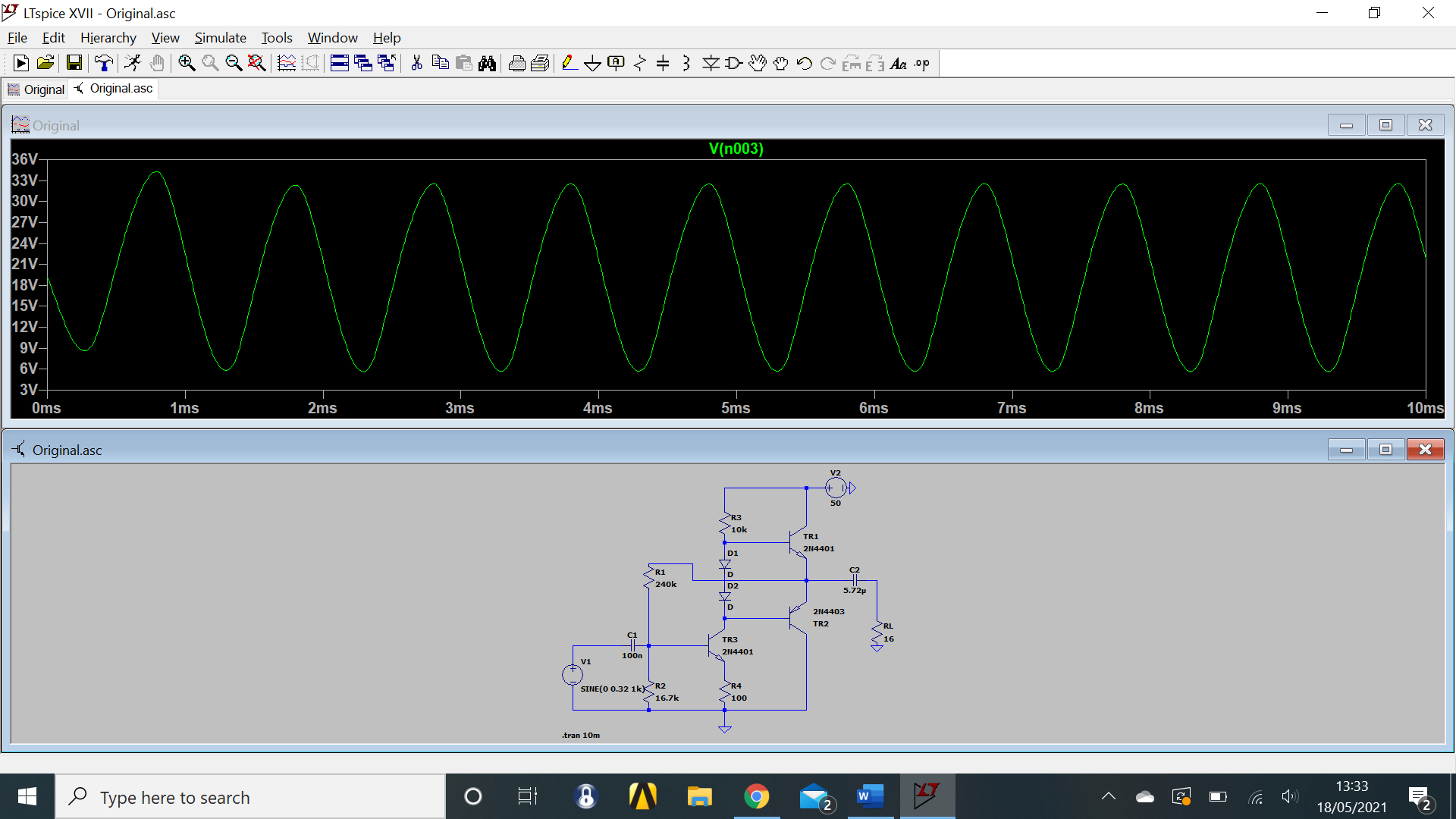
I have the following circuit design of a Class AB Amplifier which amplifies the input voltage with a voltage gain of around 42. However, I'm wanting to increase that gain to around 80. Does anyone have any tips or advice on how to do so? I've been trying to change the component values of the resistors to increase the gain however this either doesn't have an effect or distorts the signal. I've also tried making modifications to the circuit design but have so far had no luck.

Any advice would be appreciated!

LTSpice Model of Class AB Transistor

\$\endgroup\$
4
  • 1
    \$\begingroup\$ Well, these resistors where chosen to operate the transistors within a reasonable operating range; can't get infinite gain out of such a simple amplifier topology. What can save you is 1. more stages, 2. less terrible transistor choices (the maximum open loop gain you could reliably achieve with a 2n4401 would be around ~150 , which doesn't bode well for the useful amplification range in a feedback configuration), or, a completely different amplifier topology (thinking class D, seeing this is a very low-frequency amplifier \$\endgroup\$ Commented May 18, 2021 at 12:49
  • \$\begingroup\$ Hello, would you be able explain how to add more stages to these types of amplifiers? I have tried repeating parts of the circuits but haven't figured out exactly what stages need to be added. \$\endgroup\$
    – gso975
    Commented May 18, 2021 at 13:02
  • 2
    \$\begingroup\$ You and your simulation program do not know that your tiny output transistors will soon be destroyed in that circuit. They are very overloaded by voltage and current. The small output capacitor value is reducing the output level. The output impedance of the signal generator (yours has zero ohms) shorts the negative feedback causing severe distortion. Of course R4 should have a bypass capacitor for even more gain and lots more distortion. \$\endgroup\$
    – Audioguru
    Commented May 18, 2021 at 16:01
  • \$\begingroup\$ Add a bootstrap circuit electronics.stackexchange.com/questions/539546/… also you can see this electronics.stackexchange.com/questions/537846/… \$\endgroup\$
    – G36
    Commented Jan 31, 2023 at 13:27

2 Answers 2

1
\$\begingroup\$

If you want that large of a signal swing at the output, you need a better way of biasing TR3.

I would start by splitting R1 into two 120k resistors, and connecting a 10 µF capacitor between the center node and ground. This will preserve the DC negative feedback for the bias, while eliminating the AC negative feedback that's killing your gain.

If that doesn't work, a more elaborate bias circuit will be required.


Also, if you want to drive a 16 Ω load with that much voltage, you're going to need a LOT more current gain in the output stage.

\$\endgroup\$
1
  • \$\begingroup\$ Hello, I think for increasing the current gain I should be able to do this using Darlington Transistors (correct me if I'm wrong). I have tried your suggestion of splitting R1 and adding a capacitor (I assumed you meant having the two resistors in series and the capacitor connected in the middle and to ground) but so far no increase in gain. \$\endgroup\$
    – gso975
    Commented May 18, 2021 at 13:04
0
\$\begingroup\$

You can try bypassing R4. Put a 10 uF in parallel with it. Also, like Dave said, you can try other ways of biasing TR3. Rather than negative feedback biasing, you could just bias by connecting the 240k to V2 instead of the output, then play with the biasing resistor values to get to a nice Q for TR3.

\$\endgroup\$
2
  • \$\begingroup\$ Hello, thanks a lot for this, I'm up to a gain of 68 and both the voltage and current at the output look good. I'll do some more playing around with the resistor values - but thanks a lot for the help, it's moved me forward! \$\endgroup\$
    – gso975
    Commented May 18, 2021 at 13:30
  • \$\begingroup\$ @gso975 great! And welcome to electronics SE! If it works, you can accept an answer to mark the question as finished. If new questions pop up, feel free to ask more \$\endgroup\$
    – KD9PDP
    Commented May 18, 2021 at 15:16

Your Answer

By clicking “Post Your Answer”, you agree to our terms of service and acknowledge you have read our privacy policy.

Not the answer you're looking for? Browse other questions tagged or ask your own question.