1
\$\begingroup\$

I've been asked to present a possible solution to design an optical system aimed at estimating the arrival time of the following light signal:

$$s(t)=[\Sigma_{i=1}^∞rect(\frac{t-t_i}{T})]\cdot Acos(ω_0 t+φ)$$

with:

  • ω0=2π∙50MHz
  • T=100us
  • t(i+1)-ti=200us
  • Pin=-30dBm

Requirements for the amplifier:

  • Use a photodiode
  • 20Ω input impedance
  • 50Ω output impedance
  • Responsivity 0.8 A/W;
  • Minimum output voltage 100mVpp
  • Sufficient bandwidth for the input signal

What I am asking you

I do not want to ask you to do my homework. But I do not know how to start since I have lots of doubts. So, I'm asking to get some clarifications and suggestions that will help me proceed. I'll put here what I'll get with your advice. Precisely:

1. A responsivity of 0.8 A/W is required. Is it only a property of the photodiode or does it depend also on the surrounding circuitry? If I choose a photodiode with such a responsivity, can I say this requirement is filled?

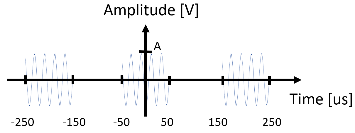
2. I've sketched the behaviour of the incident light signal:

enter image description here

Can I assume the photodiode to be linear so that the current it generates has the same behaviour?

3. About the bandwidth , I have done the following thinking. The spectrum of a rect is a sinc, and the spectrum of a train of rects is a sampled sinc. The latter will be shifted at ω0=2π∙50MHz. The main lobe of a sinc is large 1/(rect duration) = 1/T = 10kHz. Hence, if we decide to let the main lobe pass, we need an amplifier which works from 40MHz to 60MHz. Do you agree with me?

4. What might be a reason for asking a 20Ω input impedance? Is it just a casual homework requirement? As the photodiode behaves like a real current source, wouldn't be better if it were connected to a 0Ω load?

5. What is the simplest circuital topology you know which has the degrees of freedom for the requirements?

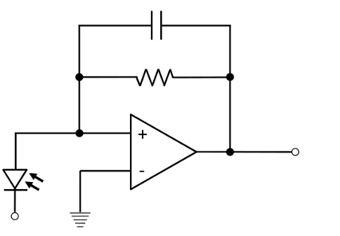
The simplest I know is this one:

enter image description here

But I would have to add a 20Ω series resistance at input and a 50Ω parallel resistance at output to fill the requirements. That does not seem to me a good idea.

Can you suggest a topology which lets me fill those requirements? The simpler the topology (also by neglecting some parasitic behaviours) the better it is since I'm newbie on this topic.

6. Does the amplifier have to be necessarily bandpass between 40 and 60MHz, or can it be also a low pass filter (from 0 to 60MHz) or high pass filter (from 40MHz) to keep the initial signal shape?

\$\endgroup\$
5
  • \$\begingroup\$ For your point 2) the light is probably like that (monochromatic), but the diode will react to the envelope, so more or less a square wave signal. But then I see that om0 is 50 MHz, that is not a frequecy for a light signal, and cannot be even the modulation of its intensity because it goes to negative values. \$\endgroup\$
    – andrea
    Commented Jun 1, 2021 at 18:12
  • \$\begingroup\$ @andrea Do you think the light should be modulated by a signal like (A+Acos(w0t+phi))? It may be a mistake of the requirement \$\endgroup\$
    – Kinka-Byo
    Commented Jun 1, 2021 at 18:21
  • 1
    \$\begingroup\$ You need to know the wavelength or spectrum of your incoming light to be able to address the responsivity requirement. \$\endgroup\$
    – Matt
    Commented Jun 1, 2021 at 18:38
  • \$\begingroup\$ You should look in to reverse biasing the photo diode. It's not clear in your schematic how you plan to bias the diode. \$\endgroup\$
    – qrk
    Commented Jun 1, 2021 at 19:00
  • \$\begingroup\$ @Kinka-Byo I only noted that there are parameters not matching what one could expect: 50 MHz is not the frequency of light (of course), it should be then a modulation of the intensity (maybe, let's say yes), but cannot be negative then. \$\endgroup\$
    – andrea
    Commented Jun 2, 2021 at 6:43

3 Answers 3

1
\$\begingroup\$

OTA’s are used to amplify current sources and the feedback R is the input resistance. The output resistance rises to the open loop Rs of any negative feedback amplifier as the gain reduces to u it’s at max GBW product thus a 50 ohm driver is a special consideration for video amps with high gain at 50 MHz and largely determined by the collector R.

As you may have already guessed -30 dBm is 1uW optical and so 0.8uA/uW into 20 Ohms is only 16uV so you need a large voltage gain with a 50 Ohm output impedance after the OTA to get your required output voltage. RC =T feedback must match RC=T of the PD for a flat response up to the GBW product (-3dB) of the OTA IC.

Parasitics of the geometric pF are also important in the layout.

That should get you started. If you get stuck , I’m sure you can find an answer with a schematic on the web, but only if you get stuck ;). You might be expected to design this with discrete FETS but you will need more than 50MHz BW.

\$\endgroup\$
2
  • \$\begingroup\$ I immediately got stuck :( With a -30dBm power, that means 1uW, the photodiode current will be 0.8uA. Is that the peak amplitude of the current signal, or the rms value? \$\endgroup\$
    – Kinka-Byo
    Commented Jun 2, 2021 at 7:09
  • 1
    \$\begingroup\$ I’m not sure , assume it’s peak power , besides what’s a few more dB when you need at least 70 dB gain or GBW=3.5GHz then factor another 6dB for 50 ohm load loss. \$\endgroup\$
    – D.A.S.
    Commented Jun 2, 2021 at 13:10
0
\$\begingroup\$

The 20 Ohm input resistance of your "transimpedance" amplifier is likely needed for stability. A photodiode may have too much capacitance to hook to the inverting input of your op-amp. It is double trouble if the photocell leads are long making a tuned circuit you don't want. You will likely need a small resistance in that path at least for stability. The capacitor across the feedback resistor can be quite small.

\$\endgroup\$
0
\$\begingroup\$
  1. A responsivity of 0.8 A/W is required. Is it only a property of the photodiode or does it depend also on the surrounding circuitry?

Property of the photodiode. For a conventional photodiode each photon gives you one electron, but since shorter wavelength photons are more energic you get fewer per watt. In addition photodiodes aren't 100% efficient, typical quantum efficiency might be in the range of 0.2 to 0.9 depending on the wavelength and semiconductor.

Can I assume the photodiode to be linear so that the current it generates has the same behaviour?

If reverse biased then yes it will be extremely linear.

  1. What might be a reason for asking a 20Ω input impedance? Is it just a casual homework requirement? As the photodiode behaves like a real current source, wouldn't be better if it were connected to a 0Ω load?

If you do a conventional transimpedance amplifier, then usually you do 0 ohms. The other option is a voltage amplifier where you have the current drop across an input resistance. In this case it sounds like they want you to do the latter but I would ask questions here, the meaning of your spec is unclear.

  1. Does the amplifier have to be necessarily bandpass between 40 and 60MHz, or can it be also a low pass filter (from 0 to 60MHz) or high pass filter (from 40MHz) to keep the initial signal shape?
Low pass would work.

\$\endgroup\$

Your Answer

By clicking “Post Your Answer”, you agree to our terms of service and acknowledge you have read our privacy policy.

Not the answer you're looking for? Browse other questions tagged or ask your own question.