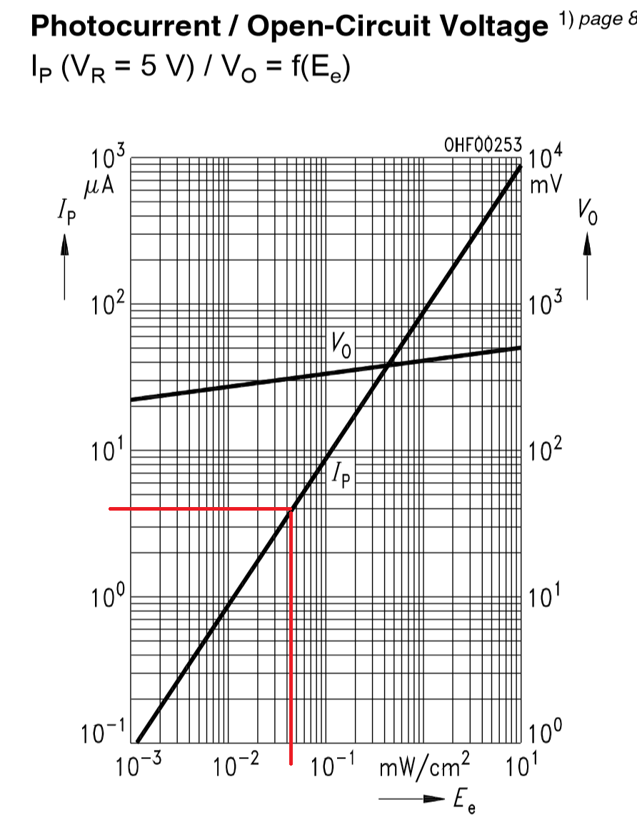
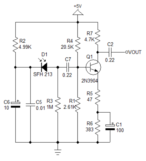
If you look at the datasheet for the SFH213 you will notice the current is specified at a particular intensity for the incoming optical signal.
You will also notice that there is a current specified as dark current.
Assuming that your diode only sees the incoming signal you could assume that it provides only the dark current when the sender LED is OFF.
So Dark current is about 1 nA.
You have not specified your LED sender, so it's impossible to speculate on what the incoming signal power level might be.
For example you might use something like a MT5900-IR LED which could have about 45 mW radiant power spread over a 20 deg cone at 100 mA drive current.
The amount of power that reaches the PIN diode active area may only be 1000'th of this total power. Obviously the amount of signal power will vary depending on how far the LED is from the PIN diode, but let us assume for the example that the inbound signal power is <45 uW/cm^2.
You can now use the graph on the SFH213 datasheet to see what current might flow with this signal.

So the signal current will vary in this example from around 1 nA to a peak of about 4 uA.
The rest of the circuit is tricky ...since you have a 1M Ohm load resistor you'd expect to get about 4 V of signal if that was the only load, but the input impedance of the transistor stage will drag this down. You would actually get only about 10 mV or so input to the transistor amplifier, and the output would therefore be around 1 V peak to peak.


