0
\$\begingroup\$

I'm designing a drone controller board and a power distribution board. The power distribution board will supply the controller board, and up to 4 (Electronic Speed Controllers)ESCs, from a 4S-6S LiPo battery. The max current target of the power distribution board will be 160A. The power must be supplied to all from the LiPo, with step down voltage regulator on controller board. I will have high speed signals on the control board such as MIPI, PCIe, and Displayport. The controller board will control the ESCs via PWM from controller board to power distribution board. Is it necessary to isolate the controller board from the power distribution board to prevent ground bounce which will negatively affect the signal integrity of the controller board's high speed signals?

Will ground bounce be induced if the ESC connectors are on one board, and the controller board is completely separate? I am unsure if the current loops induced from the ESCs in the power board will affect the signal integrity of a controller board with sensitive high speed signals.

Thanks for any tips/pointers on the subject

\$\endgroup\$
11
  • \$\begingroup\$ Kinda pointless to isolate signals without isolating the power, or isolating the power without isolating the signals. And just checking...what is your idea of isolating? You can't isolate just ground and talking like that implies a high probability that you think isolating just means not connecting two wires together. Isolation requires the involvement of extra stuff that is or is based on transformers, capacitors, light, or radio. \$\endgroup\$
    – DKNguyen
    Commented Jun 5, 2021 at 1:52
  • \$\begingroup\$ Hello DKNguyen, I was thinking of voltage isolation via a isolated DC-DC converter via a transformer. Yes I am aware that not connecting two signals is not isolation, sorry if my post did not make this clear. I am specifically concerned in high current draw/quick change in current induced by the motors affecting high speed signals that will be present on another board fed by the same battery. Edit: the only signals present on power board will be PWM for ESCs. \$\endgroup\$
    – Chance K
    Commented Jun 5, 2021 at 1:55
  • \$\begingroup\$ Okay. Then just my original comment that if you isolate one thing crossing a divide, you should isolate everything crossing that divide. That can quickly get daunting. \$\endgroup\$
    – DKNguyen
    Commented Jun 5, 2021 at 1:57
  • \$\begingroup\$ Thank you for the input. Quick question though, do you think that is necessary? Do you believe the power draw of the motors would affect the ground plane enough to cause issues on the controller board? \$\endgroup\$
    – Chance K
    Commented Jun 5, 2021 at 1:59
  • \$\begingroup\$ I don't know because it is so unusual to have PCIe and Displayport running off the same supply as a motor. \$\endgroup\$
    – DKNguyen
    Commented Jun 5, 2021 at 2:00

2 Answers 2

1
\$\begingroup\$

The power must be supplied to all from the LiPo, with step down voltage regulator on controller board... Will ground bounce be induced if the ESC connectors are on one board, and the controller board is completely separate?

If they are all supplied from the same power source than they cannot be completely separate. To prevent problems due to current flowing in the ground wires you should connect each board to the battery at a common 'ground' point close to the ESCs. That way ESC current does not flow through the control board or the power wires going to it.

If the PWM signals are sent directly from the control board to the ESCs then the voltage difference between their local grounds could be a problem. To avoid this you can isolate the signal with optocouplers. High powered ESCs often have an 'opto' option for this purpose.

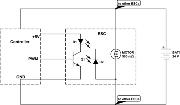
The schematic below is a greatly simplified representation of how the optocoupled system works. The input side of the optocoupler is powered from the controller, but the signal ground and power ground are separated inside the ESC. Voltage drop across the ground wire from the battery to controller or battery to ESC cannot affect the signal because the input side of the optocoupler is 'floating' at controller ground potential.

schematic

simulate this circuit – Schematic created using CircuitLab

\$\endgroup\$
1
  • \$\begingroup\$ Didn't think about difference in ground levels affecting the PWM signal. Excellent take, and pretty much what I was looking for. When you say connect both boards to a common ground, near the battery terminal, are you essentially ensuring the high current loop will only go from ESC to battery terminal, avoiding traveling up the connector and going to the controller board? \$\endgroup\$
    – Chance K
    Commented Jun 6, 2021 at 14:51
1
\$\begingroup\$

Isolation is your tool to make sure crazy currents don't trigger digital signals or mess with analog signals. Since it's "just" a drone, you don't need isolation same way it's required in industrial applications.

So to your question, if you can be sure you design the current flow such a way you don't get grounds bounced each time a motor is turned on, you don't need isolation. But if you feel you don't even know what I am talking about, I suggest using isolation and local grounds for command signals. It's not that much expensive, especially if you have four 160A devices.

Upd. If you use strictly star connection, you may get away without isolation. However it's nearly impossible if you have a lot (not sure where the threshold is, somewhere) of signals running between the modules.

And in any case, with such currents you don't have a single ground node. Each module will have it's own ground. Be sure not to allow currents from ESC to run anywhere but thick wires and the battery.

\$\endgroup\$

Your Answer

By clicking “Post Your Answer”, you agree to our terms of service and acknowledge you have read our privacy policy.

Not the answer you're looking for? Browse other questions tagged or ask your own question.