0
\$\begingroup\$

I'm trying to figure out a way to detect if a RJ45 cable is connected, and report that to a microcontroller. I'm not using the IP standard, I'm purely using the cable for the ease.

A bit of reference:
I'm using all 8 conductors. 2 for 12 V, 2 for GND, and 4 for buttons. (Basically it's 4 buttons on a long wire.)

Is there a way for the sending device to detect when the cable is connected?

Edit:
Could I use a current sensing circuit?
Then on the button PCB add a cap and an LED. That way I could detect the ~18 mA draw when the cable is plugged in.

\$\endgroup\$
2
  • \$\begingroup\$ Just the cable, or the buttons at the other end? In the latter case you could apply a small permanent load on one or more of the buttons and add a circuit to detect it. The former would be more of a challenge, but possible. \$\endgroup\$
    – Frog
    Commented Jun 5, 2021 at 6:56
  • \$\begingroup\$ "2 for 12v 2 for gnd" Is that coming in from the other end? Or from here going out to the other end? \$\endgroup\$ Commented May 26, 2023 at 0:25

1 Answer 1

1
\$\begingroup\$

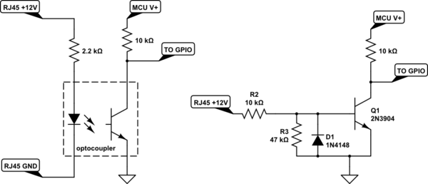
Seems like a simple optocoupler arrangement would work for you:

schematic

simulate this circuit – Schematic created using CircuitLab

You could also just use a transistor if the grounds are shared between the MCU and RJ45 cable. If you do so you should add a diode as shown. Long wires are susceptible to picking up RF energy and the diode will protect the base of the transistor from negative voltage spikes.

If the RJ45 cable is not connected the GPIO line will be HIGH. Otherwise it will be LOW.

\$\endgroup\$
4
  • \$\begingroup\$ So it should work with a mcp23017 too ,by default im using external pullups so my butons pull down to ground \$\endgroup\$
    – bedrock
    Commented Jun 5, 2021 at 7:22
  • \$\begingroup\$ But my ground is shared so a transistor might be the way \$\endgroup\$
    – bedrock
    Commented Jun 5, 2021 at 7:26
  • \$\begingroup\$ Answer updated with transistor circuit. \$\endgroup\$
    – ErikR
    Commented Jun 5, 2021 at 11:30
  • \$\begingroup\$ Use pull up resistors on each button. On the receiving side you need to measure the voltage and see if you have several volts available. If all 4 buttons could be maintained then you need some delay. The other option is use one of the power leads as a return to your module. If using + add a pull down resistor and in hour controler measure the voltage. It could be conditioned and become a logic input. \$\endgroup\$
    – Gil
    Commented Jan 22, 2023 at 2:31

Your Answer

By clicking “Post Your Answer”, you agree to our terms of service and acknowledge you have read our privacy policy.

Not the answer you're looking for? Browse other questions tagged or ask your own question.