1
\$\begingroup\$

I am designing a system for a 3.5 kW wind turbine that has a large input voltage range, from 0 up to say 750 VDC. The output voltage should not exceed 600 VDC. I would like to make a voltage limiting circuit. Do not worry I do not test any of this in my barn or backyard. I do my experiments in a university in a laboratory environment surrounded by professionals.

I came across some problems for this application:

I believe ideally the buck converter should do nothing (gets bypassed) up to 600 VDC. The reason is that operating the buck converter introduces energy loss which I want to avoid. Bypassing seems not to be very simple:

  1. Using a relay at this DC voltage there is a lot of arcing, a relay wears out quickly and it is also dangerous.
  2. Using a semiconductor such as a power MOSFET or IGBT requires high side switching. High side switching with a bootstrap circuit does not work if you would like to have the switch fully closed (duty cycle = 1). Using a charge pump is possible I believe, but the typical ICs go up to 60 VDC. I could design a high voltage charge pump. This is not my preferred choice since I think it is going to be difficult to properly and reliably control expensive and delicate power electronics.
  3. Perhaps using a P-channel MOSFET would be more do-able. The R_on resistance losses are bit higher but perhaps could be acceptable. However, they do not seem to be available for such high voltages.
\$\endgroup\$

2 Answers 2

1
\$\begingroup\$

Any ideas, suggestions or comments?

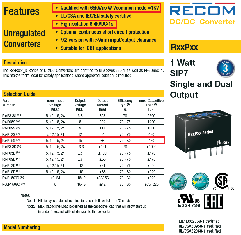
I would use a little dc-to-dc converter to produce (say) an isolated 15 volts supply for the high side MOSFET switch. Ones that are definitely suitable and superior are Recom's RxxPxx series of 1 watt converters: -

enter image description here

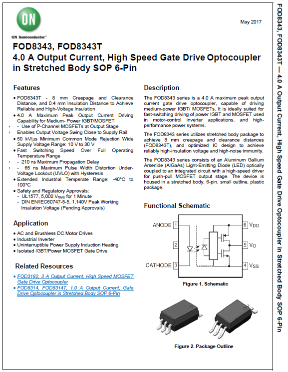
This means you can use an N channel MOSFET (more available at 1200 volt rating for instance). Then, I'd us an FOD8343 high-speed gate drive opto-coupler to control the MOSFET and provide bags of isolation: -

enter image description here

For the switching element I'd probably use a TO-247 SiC 1200 volt N channel MOSFET. You can get on-resistances as low as 20 milli ohm and this seems like it would fit the bill (3500 watts and 750 volts implies a current of about 5 amps).

You also have to be fairly conservative on voltage ratings; even a short wire (inductance) and moderate di/dt can easily cause transients of a couple of hundred volts that sit on top of the 750 volts. You can easily eat into 1200 volts is what I'm trying to say.

Then, I'd probably consider making this device the buck regulator switch and ensure that when the voltage dropped below 600 volts, the device stayed on (something that a buck converter naturally does by the way).

If you are switching fast, you have to consider the isolation component's (Recom and FOD8343) transient immunity and both the device recommended above are as good as any I can find.

\$\endgroup\$
4
  • \$\begingroup\$ Thank you for your reply. I do not get how this 15 Vdc could drive the gate. Since the gate voltage should be higher than the source voltage to close the switch. \$\endgroup\$ Commented Jun 16, 2021 at 8:54
  • 1
    \$\begingroup\$ The dc-to-dc converter has an isolated output hence the negative end can directly attach to the MOSFET source. Does it become clearer now @WillyBogard. If you wish, just regard the dc-to-dc output voltage like a battery (with infinite energy) that can be taken up to any voltage that you want. \$\endgroup\$
    – Andy aka
    Commented Jun 16, 2021 at 9:18
  • \$\begingroup\$ Thanks yes that would make sense! Its floating onto the negative end. \$\endgroup\$ Commented Jun 16, 2021 at 9:35
  • 1
    \$\begingroup\$ @WillyBogard Look here: ti.com/tool/TIDA-01160 and Google: "isolated gate driver" pay attention to the max. isolating voltage. \$\endgroup\$ Commented Jun 16, 2021 at 10:59
1
\$\begingroup\$

There is option 4: use a small isolated DC-DC converter for your high-side gate driver. These are transformer-coupled so you get quite high voltage isolation.

\$\endgroup\$
1
  • \$\begingroup\$ Ah thanks I will look into it and consider this option as well! \$\endgroup\$ Commented Jun 16, 2021 at 8:22

Your Answer

By clicking “Post Your Answer”, you agree to our terms of service and acknowledge you have read our privacy policy.

Not the answer you're looking for? Browse other questions tagged or ask your own question.