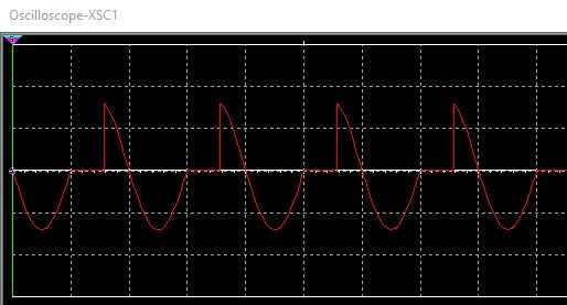
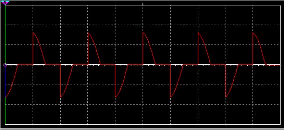
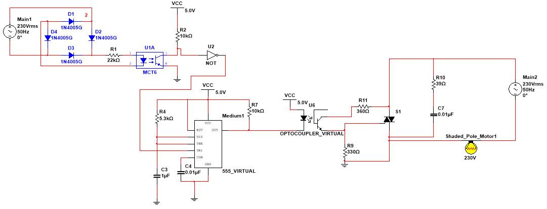
I have designed a speed control circuit for an induction motor. The circuit consists of a zero cross detector circuit whose output pulse is the input to a 555 timer. The 555 timer is used to generate a PWM wave that is then inputted into an optocoupler. The TRIAC control circuit then applies a chopped AC waveform to the induction motor. The 1st picture is the chopped waveform (incorrect) applied to the motor (used lamp in multisim as there is no motor), the 2nd picture is how the chopped waveform should look and the 3rd picture is the circuit diagram. I am having trouble (with the negative half cycle) with getting the waveform in the 1st picture to look like the correct waveform in the 2nd picture. Can you guys please help me fix the design?


3 Answers
The opto-isolator you are using will not function correctly when the voltage is reversed.
The base-emitter junction of the isolator will break down with only a few volts negative and then drive current into the triac so turning it on and giving the result you are seeing.
-
\$\begingroup\$ Ah, I see, do you have any suggestions for which optoisolator to use? \$\endgroup\$ Commented Jun 23, 2021 at 20:24
-
\$\begingroup\$ You're looking for an opto-triac instead of an opto-transistor. \$\endgroup\$ Commented Jun 23, 2021 at 20:31
-
\$\begingroup\$ I've tried to replace the MCT6 optoisolator with the MOC8101, however, I get an error when trying to run. \$\endgroup\$ Commented Jun 23, 2021 at 20:31
-
\$\begingroup\$ @Daelin, I get "an error" isn't anything to go on. Edit your question, add in a schematic of your new configuration and details of the error. The MOC8101 is another transistor opto-isolator. Why are you trying to use that? \$\endgroup\$ Commented Jun 23, 2021 at 21:05
-
\$\begingroup\$ @Transistor Apologies, I am fairly new to multisim so I'm not entirely clued up with all the components on there. Do you have any recommendations on which opto-triac I could use? \$\endgroup\$ Commented Jun 23, 2021 at 21:08
I switched out the virtual optocoupler for the MOC8101_BASSO and everything worked perfectly.
-
\$\begingroup\$ Beware, simulated parts don't always have all the characteristics of the real part. MOC8101 has CE breakdown voltage of 30V and EC breakdown voltage of 7.0V. The real part will not handle 230VAC! \$\endgroup\$ Commented Jun 24, 2021 at 8:26
A better management of the triac is to control it with a negative power supply and keep the optotransistor. This way you keep a low voltage driver and control the triac on Q2 and Q3. It requires to add a wiring to the psu to get the negative voltage but in term of topology robustness, it leads to better results, especially regarding noise immunity, because optitriacs usually suck for dv/dt.
