2
\$\begingroup\$

I try to rebuild an electronic board for an old potter's wheel. I try to build a "Phase Angle Control" with BTA16-800BWRG and MOC3043SR2M to control motor speed (the old board seem to use this principle).

Here is the old factory board :
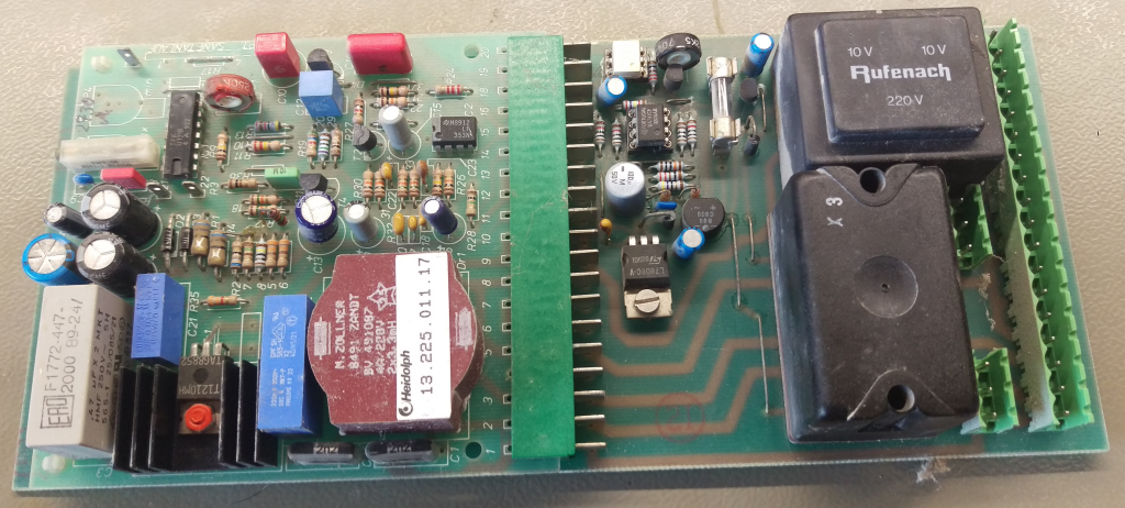
Old Factory Board
Here is the full schematic of the old board

Here is my homemade new board :
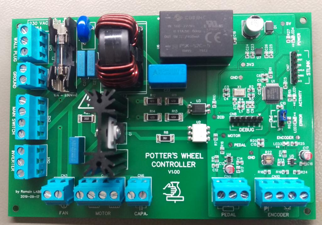
My homemade new board
Here is the full schematic of the new board

For instance I use filament light to build the firmware but I got problem, my output stage work only when I do measurement. (I use transformer to check signal with my oscilloscope).

  • When I plug the transformer to isolate and see signal between pin 4 and 6 of the MOC3043 the signal on oscilloscope almost look like I was expecting and filament light is lighting (depend on pulse characteristics), all is OK while a leave transformer connected.
  • When I remove the transformer the filament light is completely off, and when I try to see signal at the terminals of the lamp (with my isolation transformer) I got no signal at all.
  • When I put the transformer at the load, filament light stay off and I got no signal at all.
  • When I put the MCU pin "motor" at steady high level, the filament light is lighting and I can get signal with transformer at the load. (I got the full 50Hz wave without glitch)

To sum up, I'm be able to steady glow light with steady high level on "motor" pin, on when I put transformer on pin 6/4 of the MOC3043 when I pulse the gate with pulse signal synchronized with a zero crossing detector.

This is the first time I use TRIAC and I don't understand what append.

Here is the interesting schematic part :
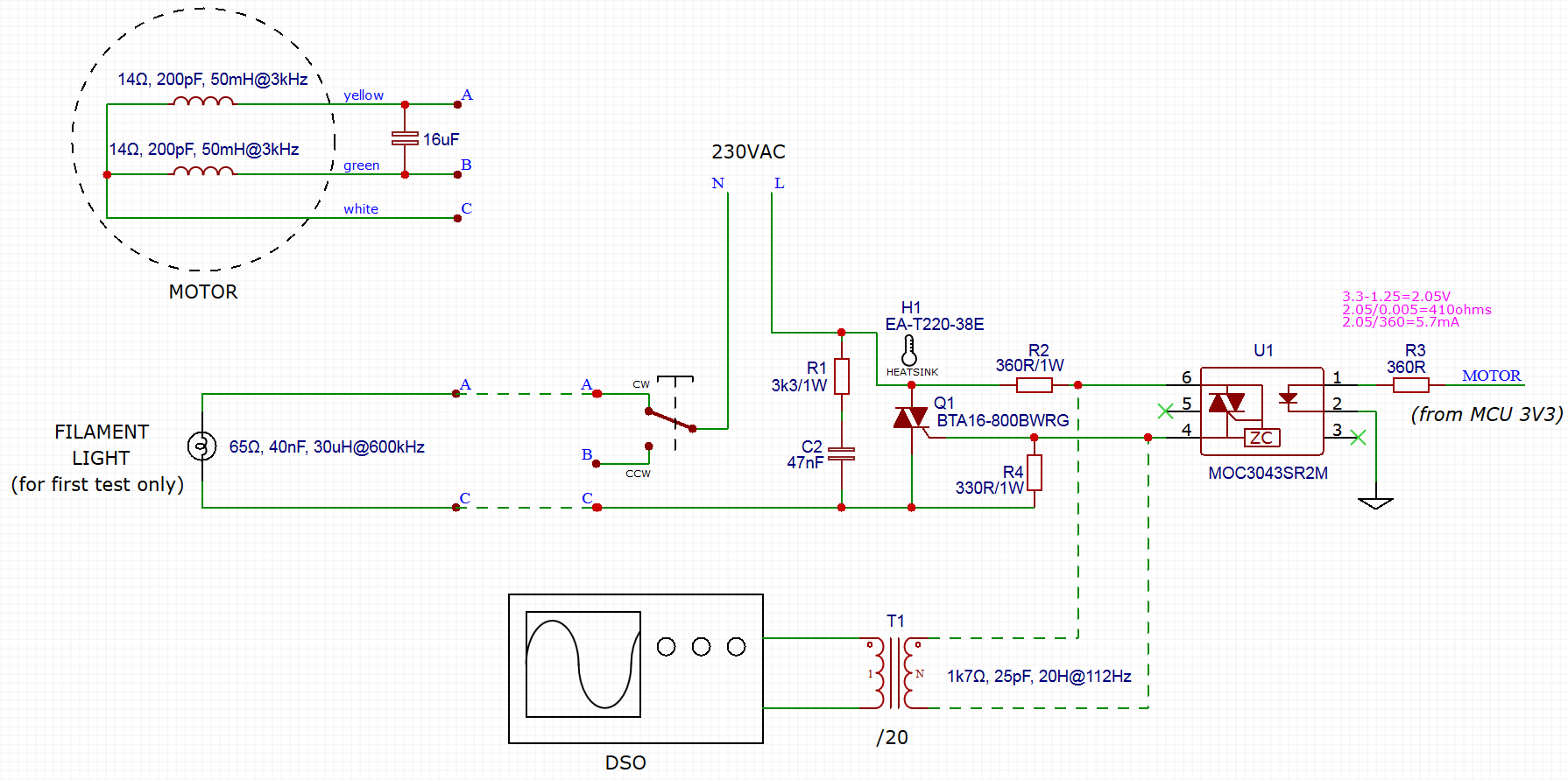
Phase Angle Control Schematic - Only filament light OR motor (with 16uF capacitor) is connected at the same time.
- The motor, light and transformer characteristics came from measurement with ohmmeter and LC100-A
- I try with and without R1

Here is the TRIAC gate signal with the /20 isolation transformer :
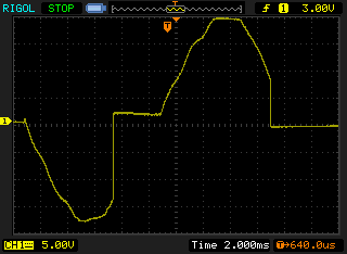
TRIAC gate signal
I could not get both signal (gate and load) because I got only one transformer

Here is the MOC3043 command signal :
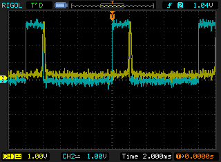
MOC3043 command signal
In yellow : The zero crossing detector signal entering the MCU
In blue : The "motor" pin signal from the MCU. I know high level of pulse is very long but it's to be sure TRIAC is really fired

Can someone help me to solve the problem and calculate the right value for components for filament lamp and for motor ?
(I'm more comfortable with software than hardware, I need help)

EDIT 2019-11-29 (1)

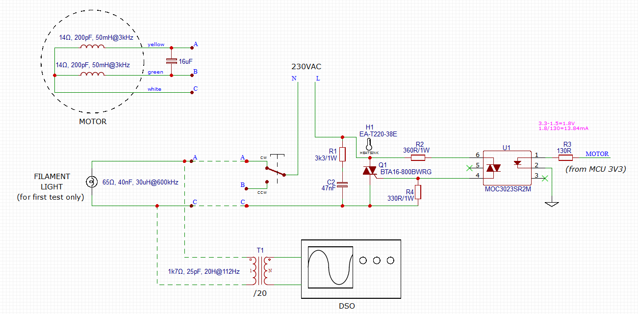
Thank to I directly replace the MOC3043 by MOC3023 (without zero-crossing trigger) and I replace R3 by 130 ohms resistor to increase current in led to 14mA.

Here is the new schematic :
New schematic

Now I'm able to control the phase for the filament light. YipHa !

Here is the signal at load with the /20 isolation transformer :

Phase controlled signal

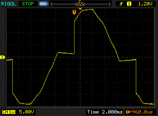
All is not perfect, I got some random glitch. Sometime the light quickly glow strongly. I use my transformer to capture the glitch

Here is the glitch capture at load with the /20 isolation transformer :
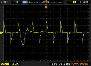
Triac glitch
We can clearly see the glitch, the phase continue after crossing down to zero.

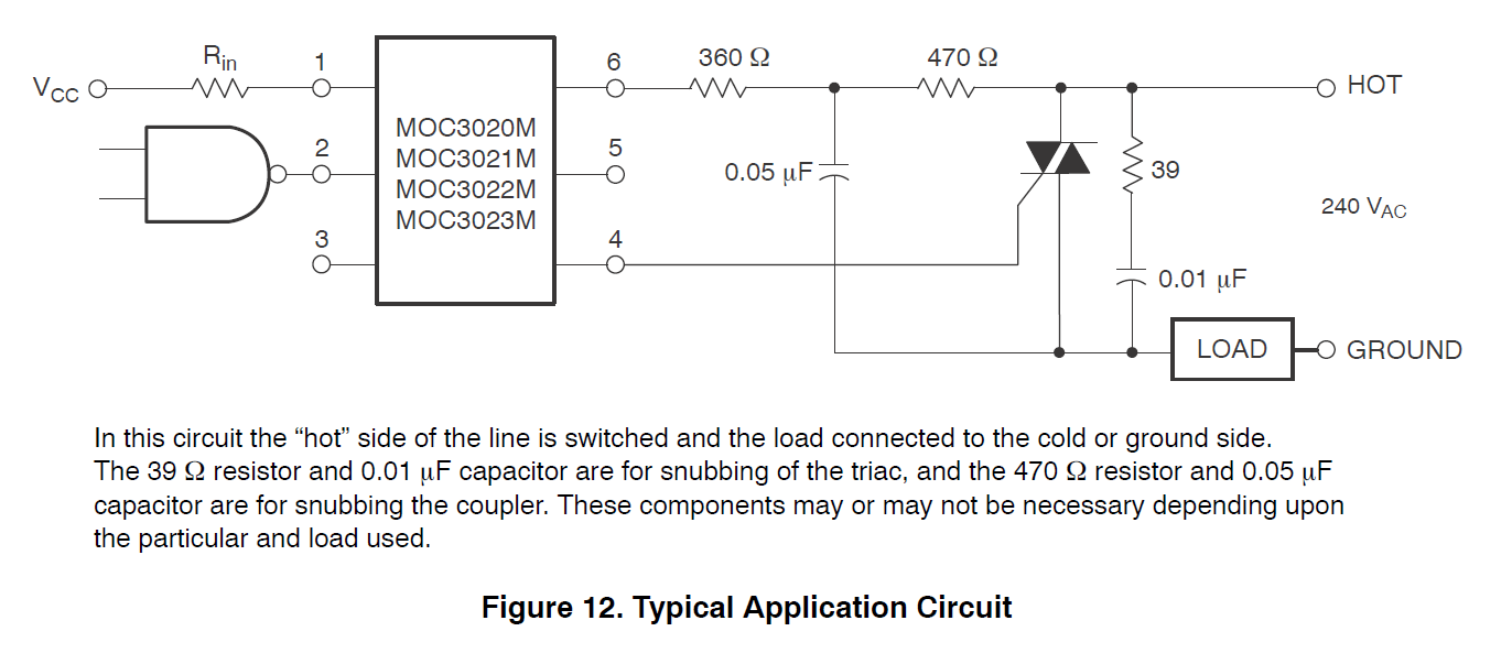
I don't think glitch came from my firmware, I could not implement the supplier recommended schematic for instance page 7 of MOC3023 datasheet

Here is the recommended schematic :

MOC3023 datasheet recommended schematic

Do you think glitch can come from the lake of snubbering the MOC023 as it recommended on schematic ?

EDIT 2019-11-29 (2)

My glitch problem came from software problem, I try to "hand" build the pulse from a STM32 timer triggered by zero crossing interrupt. I update the timer period twice for low and high level of pulse with complicated "state machine" automaton. I got jig from flash latency and interrupt preemption.

Now I use a simple "output compare" timer (OC) in "one pulse" mode, and the output signal is very stable now use much less resources. Ready to implement motor control algorithm like PID or other algorithm...

I think I will re-route the board with the recommended MOC3023 schematic

\$\endgroup\$
12
  • 1
    \$\begingroup\$ Please describe the filament lamp. How may watts is it? Circuits of this type require a minimum load to operate properly. \$\endgroup\$
    – Mattman944
    Commented Nov 27, 2019 at 1:48
  • 1
    \$\begingroup\$ poutting a transformer there will trigger the triac, reduce R3, I think you need more current through the opto-LED \$\endgroup\$ Commented Nov 27, 2019 at 2:14
  • 1
    \$\begingroup\$ @Jasen The MOC3043SR2M datasheet specify IFT (Led trigger current) to 5mA, do you think a need more room to properly trigger the TRIAC ? \$\endgroup\$
    – rom1nux
    Commented Nov 27, 2019 at 10:17
  • 1
    \$\begingroup\$ What does the signal from the MCU look like? Did you try connecting it directly to 3.3V instead? \$\endgroup\$
    – Mattman944
    Commented Nov 27, 2019 at 18:01
  • 2
    \$\begingroup\$ (3.3-1.5)/360 is indeed 5mA right at the minimum. allowing for 5% variance in the resistor, the logic supply voltage, or for any resistance in logic output could put you under the minimum - I suggest 220 or even 100 for R3 instead. Aim between the goal posts \$\endgroup\$ Commented Nov 27, 2019 at 20:12

1 Answer 1

4
\$\begingroup\$

If you want phase control, you can't use a zero-crossing optocoupler. They are designed to prevent phase control to minimize switching noise (EMI). Try a MOC3052-M instead. You will need to lower R3 significantly to get 10 mA. And don't aim for just 10, aim for 15 or more. My version of Jasen's quote -- aim between the goal posts (great quote, I may borrow it) is when margin is cheap, put in a lot.

Edit: Glitch issue: Put the optocoupler input on the scope at the same time. If the trigger pulse from the MCU extends into the next half-cycle, the next half-cycle will be full.

Make sure that your MCU zero-cross detector is not sensitive to noise. The AC input (mains) can have a tremendous amount of noise on it, your design needs to deal with this. This can be done in hardware or software.

\$\endgroup\$
9
  • \$\begingroup\$ Arf ! This is a really bad mistake. I got this small bloc "ZC" on MOC3043 symbol in front of my eyes without the light coming on in my head. Many thanks for this. I have to review my schematic. \$\endgroup\$
    – rom1nux
    Commented Nov 27, 2019 at 21:54
  • 1
    \$\begingroup\$ @rom1nux your schematic seems ok, but the recommended schematic is the one that I use. AC motors are bad beasts, you should accept some (acceptable) glitch, and pay attention to the zero crossing detection. The blue track on the scope shows that you are keeping the opto ON for too much time, leaking in the next cycle. You could instead use a short pulse (microseconds), the triac will shut off automatically; that way it is easier to optimize the firmware. \$\endgroup\$ Commented Nov 29, 2019 at 11:02
  • 1
    \$\begingroup\$ @rom1nux just a note for PID: by varying the phase you (kind of) vary the voltage to the motor, but in reality you vary the torque (in a non-linear way, too!). AC motors are not well suited for PID, but you will discover it by yourself... I'been happy to help. \$\endgroup\$ Commented Nov 29, 2019 at 15:35
  • 1
    \$\begingroup\$ @rom1nux I don't know any alternative to PID, which will mostly work, probably a little (or very) loosely. Problem one is, you can not brake (you must invert the relay, don't do it too often). Second problem: give the motor a phase (command) X, and it will not move; give little more than X, and it will nearly reach its top speed. Worse, the same command will produce different torques at different speeds. Experiment first: every final application can be different. \$\endgroup\$ Commented Nov 29, 2019 at 17:45
  • 1
    \$\begingroup\$ @rom1nux for a standard PID, consider the D component, it should help. \$\endgroup\$ Commented Nov 29, 2019 at 17:46

Your Answer

By clicking “Post Your Answer”, you agree to our terms of service and acknowledge you have read our privacy policy.

Not the answer you're looking for? Browse other questions tagged or ask your own question.