1
\$\begingroup\$

Schematic

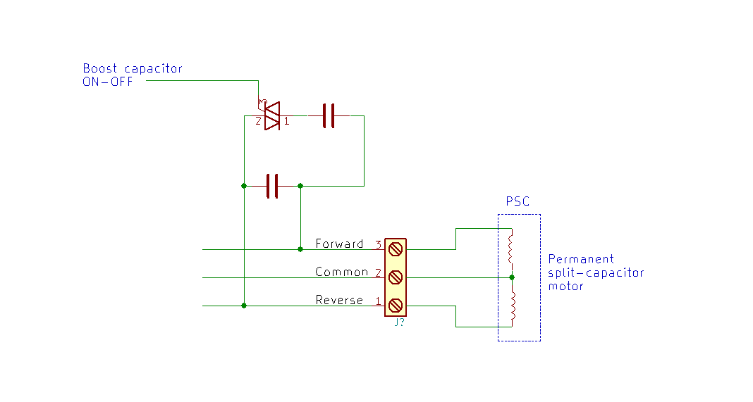
In the image above, we see a PSC motor, with its 3 terminals, connected to a control board. This board has a RUN capacitor always connected to the motor. When the motor has to turn, the board applies 230V AC between the COMMON line and either the FORWARD or REVERSE line. The relevant winding is powered directly, and the other winding gets powered via the RUN capacitor, with about 90 degrees delay. This makes the motor run in one of the two direction.

What I want to do is to connect, in parallel to the first, a second capacitor in order to boost the torque (when the motor is starting). After a little time the motor is started, this added capacitor should be disconnected.

I would like to use a TRIAC instead of a relay. Can anyone point me to choose the correct device, and give any warning I may need? I've already tried, but the TRIAC fails in short-circuit without heating or other signs (the real schematic is not simple as the one above, but the concept is exactly that).

The motor is about 1kW, @230V; the capacitors should be about 25 uF each. The current is about 1A continuous but it can rise to 4A when the motor starts or when the load gets heavy (I'm using a workbench brake for testing).

EDIT: The driving part is like this: enter image description here Basically, the 2nd capacitor has a series triac; the triac is gated by a MOC, taking current from A2 (MT2); the resistor from gate to A1 (MT1) is optional.
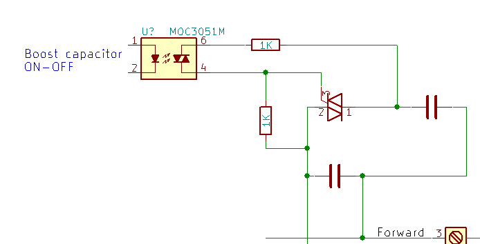
The Triac goes short-circuit, but the MOC keeps to work. The capacitors, which are normally used and considered reliable, are rated 470V. My triac is an ST, snubberless, rated 1200V and 16A (continuous). There is something I don't grasp...

\$\endgroup\$
2
  • \$\begingroup\$ Please show a more complete schematic including the gate drive circuitry. \$\endgroup\$ Commented Mar 18, 2019 at 16:11
  • \$\begingroup\$ @SpehroPefhany - added, TY. \$\endgroup\$ Commented Mar 18, 2019 at 16:23

3 Answers 3

2
\$\begingroup\$

Because you appear to have a random phase turn-on you have no control of the point of turn on. This can result in very high circulating currents between the two capacitors in the circuit you show.

You need to put a zero crossing detector across the permanently in place capacitor and use this signal to tell you when you can turn on the TRIAC. If you turn on the TRIAC when the voltage is low, then there will be no (or at least very low) circulating currents.

\$\endgroup\$
2
  • \$\begingroup\$ Thank you Jack. Do you think that a zero crossing optotriac would do the trick? That would be an elegant solution I think. \$\endgroup\$ Commented Mar 19, 2019 at 7:32
  • \$\begingroup\$ @linuxfan I doubt that another optotriac would help you. I see two ways to solve the problem ...1) A simple series resistor in the switched cap to limit the surge current, perhaps 1-2 Ohms ...2) An optoisolator ZC detector across the fixed cap with a signal to your MCU. \$\endgroup\$ Commented Mar 19, 2019 at 15:13
1
\$\begingroup\$

I suspect that snubberless means that the traic does not need dv/dt snubber but still may need di/dt protection. Switching capacitors will result in high di/dt. That is probably the mode of failure. You will need to add di/dt protection to the circuit or use a relay. A higher current triac might work without di/dt protection.

\$\endgroup\$
3
  • \$\begingroup\$ TY Charles. Actually, if the triac is excited when the run capacitor is charged, a lot of current goes to the charged cap to the empty one. What could be a way to add di/dt protection? \$\endgroup\$ Commented Mar 19, 2019 at 7:29
  • \$\begingroup\$ For di/dt protection, a small amount of series inductance is required. A couple of turns of wire around a ferrite core might do it. I would be inclined to look for a zero-crossing solid state relay instead. \$\endgroup\$
    – user80875
    Commented Mar 19, 2019 at 13:39
  • \$\begingroup\$ The zero crossing option is interesting, I will try. I also thought to SSR's, but then I saw the prices... hope I find something less expensive. TY for the inductance idea. \$\endgroup\$ Commented Mar 19, 2019 at 13:49
0
\$\begingroup\$

Why are you attempting to re-invent this circuit? What problem are you trying to solve? How are you planning on deciding WHEN to disconnect the capacitor?

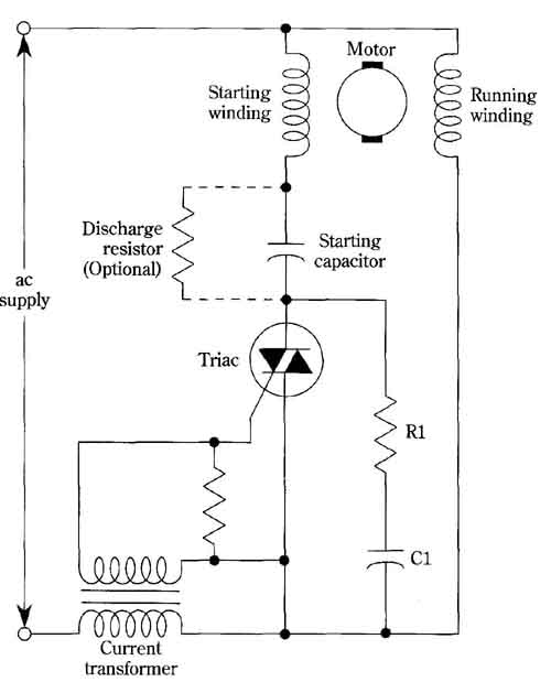
From the standpoint of the triac/SCR, the charging current of the capacitor looks like a short circuit and the resultant dI/dt can damage the thyristor, then when you turn off the triac/SCR, the inductive kickback from the motor winding can cause a dV/dt issue. Preventing all of that is going to cost more than the potential benefits of changing to a triac/SCR, which is why you do not see this concept used by motor mfrs.

FYI, GE developed this concept a long time ago and abandoned it as being actually LESS reliable than the electro-mechanical method.

GE's circuit, includes RC snubber and discharge resistor. enter image description here

\$\endgroup\$
3
  • \$\begingroup\$ TY for this useful info. I am reinventing because I didn't know of this GE circuit. The problem to solve is to boost the torque when needed. Hence, connect/disconnect the cap. Typically, the cap is inserted before starting the motor, and removed when the motor finishes the acceleration ramp, but it could be useful in other situations too (the circuit has a CPU). As you see my aim is clear. If possible, I would avoid a relay, just because I prefer solid state. \$\endgroup\$ Commented Mar 20, 2019 at 7:25
  • \$\begingroup\$ The starting cap is mainly there to create a virtual phase shift because a single phase induction motor will not spin without it. The fact that it increases the torque during starting is mostly because it is improving the power factor of the motor when the slip speed is high, i.e. starting from a standstill. Adding the capacitor back in after the motor is already at slip speed will not have much of an effect on torque. \$\endgroup\$
    – JRaef
    Commented Mar 20, 2019 at 19:03
  • \$\begingroup\$ I've tested different motors and caps on a specific workbench equipped with electric brake, torque meter, speed meter, amperometer and so on. I can assure that, depending on situation, different cap values give different performances. All I want is to have two cap values changeable at will, possibly using a triac. I could be happy also with just inserting the boost cap before start, and exclude it after ramp up. \$\endgroup\$ Commented Mar 21, 2019 at 8:30

Your Answer

By clicking “Post Your Answer”, you agree to our terms of service and acknowledge you have read our privacy policy.

Not the answer you're looking for? Browse other questions tagged or ask your own question.