0
\$\begingroup\$

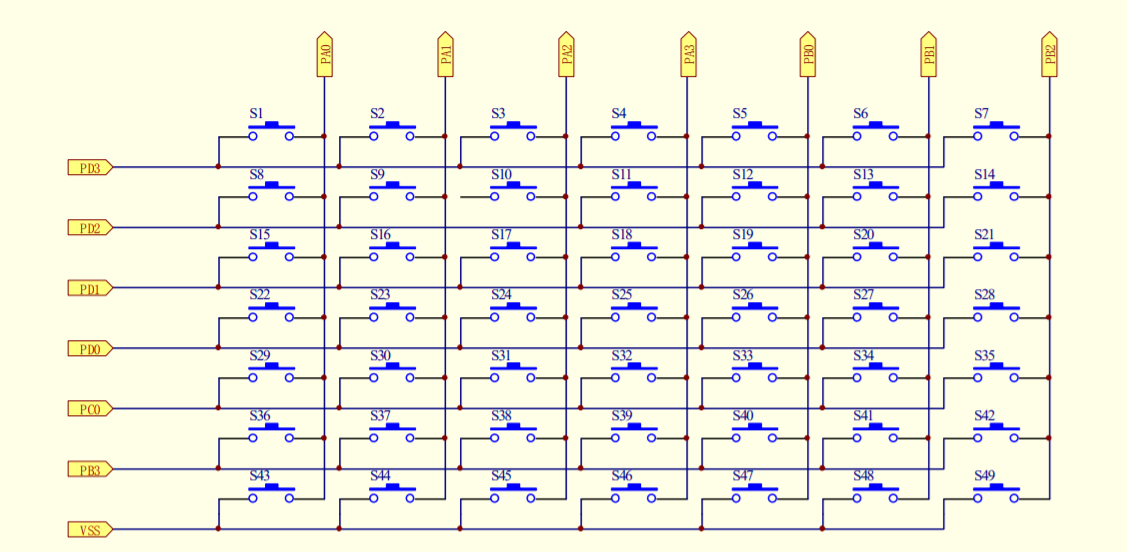
enter image description here

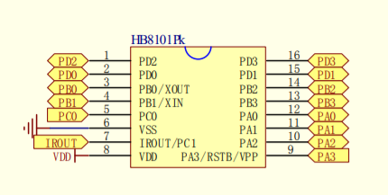
enter image description here

I'm trying to use an Arduino with a 2n2222 npn transistor to replace the functionality of S1 in this diagram. This is the schematic for my TV remote. I want to replace the physical switch with a digitally controlled one.

PD3 and PA0, according to the datasheet are pulled up to VCC (3v in this case) with a 150k resistor.

Is it possible to use a NPN transistor as a switch in this case? My intuition is no, because there's to voltage difference between the two things I'm trying to connect.

If it's not possible to use a NPN, or any BJT, what other kind of electronic switch could I use here? I could probably use a solenoid or something, but I'd love to use a transistor based solution.

The IC used for this TV remote circuit is HB8101Pk.

\$\endgroup\$
3
  • \$\begingroup\$ I've always been able to use a BJT (not necessarily always an NPN, though) to fake out a switch like this. It doesn't usually have to be a perfect switch. It just has to satisfy some conditions you need to work out, in detail. I'm fairly sure you can make the idea work. In this case, an NPN would probably work. Why don't you try? \$\endgroup\$
    – jonk
    Commented Jul 10, 2021 at 16:46
  • \$\begingroup\$ Do note that a transistor has Vbe of about 0.7V, so it might be difficult to use a BJT for a button matrix. If you only need to push one button, why not use an analog multiplexer? If you wanted to push any of the 49 buttons, since that is only a 7 by 7 matrix, you can simply use two chips, eight channel analog muxes, to push any button. Even more safe solution would be to record the button code and play it back on some MCU so you don't have to physically do anything to your TV remote, not even open it. \$\endgroup\$
    – Justme
    Commented Jul 10, 2021 at 17:12
  • 1
    \$\begingroup\$ I recommend using an analog switch IC as the CD4066 for this purpose. \$\endgroup\$
    – Janka
    Commented Jul 10, 2021 at 20:50

3 Answers 3

2
\$\begingroup\$

According to the datasheet PA3 is input only. That means in the application circuit shown PD3 must be an output pulling low, and PA0 should also be an input with pullup. Therefore if your remote control follows the same scheme you should be able to do this:-

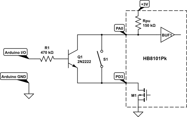
schematic

simulate this circuit – Schematic created using CircuitLab

I have shown part of the the equivalent internal circuit of the HB8101Pk so you can see how it works. When the MCU wants to scan the top keyboard row it turns on M1 to make PD3 low. If S1 or Q1 is on then it is effectively a short circuit which pulls PA0 down to PD3. R1 is required to limit Base-Emitter current to a low value that the MCU can handle, but high enough to turn the transistor on fully with a 150 kΩ load.

To avoid injecting higher voltage into the HB8101Pk you should arrange the Arduino I/O to be no more than 3.9 V (eg. by using a 3.3 V regulated Arduino or powering it directly from a 3 V battery), or use a voltage divider to reduce the I/O voltage to less than 3.9 V.

This circuit should work if the MCU is configured as shown. For a more generic circuit that will work with any keyboard no matter how it is scanned, you could use either an 'analog switch' such as the CD4066 or 74HC1G66, or a PhotoMOS 'solid-state relay' such as the Panasonic AQY210EH. Opto-isolation requires more power when operated, but has the advantage that you don't have to worry about having compatible voltages and a shared ground.

\$\endgroup\$
2
\$\begingroup\$

If you don't want to spend too much time determining how the IC is detecting switch closures, you could just mimic the S1 switch closure using an analog switch (SPST would work for you). You can search for "transmission gate" but basically it is an analog switch that lets current flow in either direction when "closed", and can be controlled by a logic signal. As long as you choose an analog switch whose on resistance is sufficiently smaller than the 150k resistors than it should appear to the circuit essentially the same as a closure of S1. As always you need to make sure your logic circuit to open and close the switch has the same ground as the remote circuit but that should be all you need.

\$\endgroup\$
1
\$\begingroup\$

You might be able to but you would have to figure out the scanning works on those buttons. Is SW 1 sensed via PD3 or PA0? An N-channel MOSFET would probably work better (for example the BSS138). The ports all have pullups, but then either PA0 or PD3 must be driven low to detect if SW1 is pressed. Connect the NMOS source (or NPN emitter) to whichever one will be driven low, and the drain to the one that is used for sensing. A control signal that you supply to the gate (or base) will determine whether the transistor is on or off. If you use an NPN BJT, then you need a resistor in series with the base.

\$\endgroup\$

Your Answer

By clicking “Post Your Answer”, you agree to our terms of service and acknowledge you have read our privacy policy.

Not the answer you're looking for? Browse other questions tagged or ask your own question.