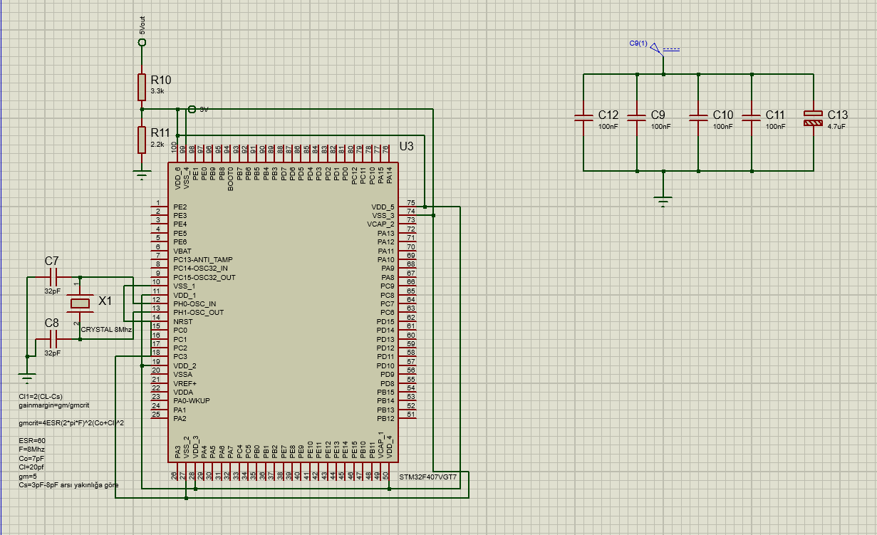
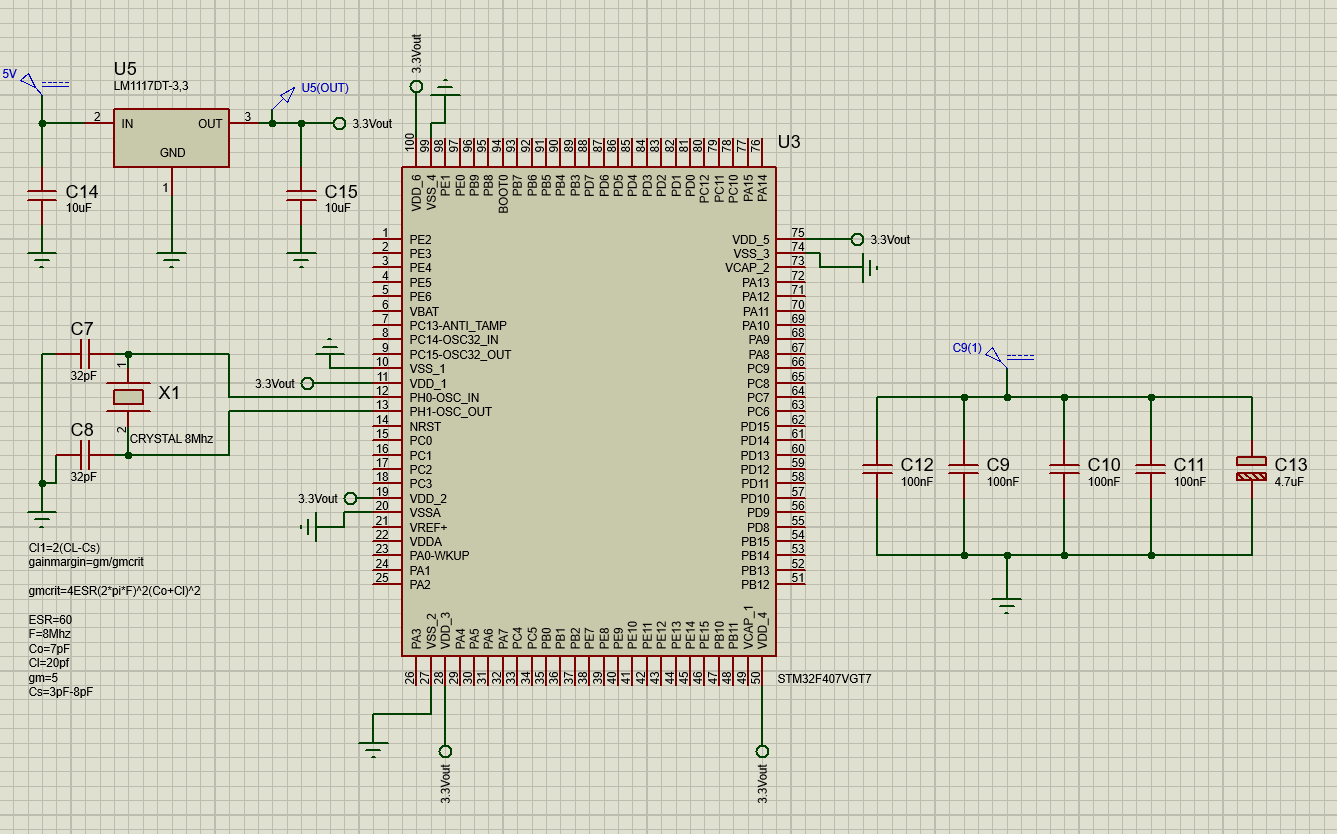
I am going to use STM32F407VG in my PCB design. I have never done it so that i don't know how to do it.
ST provides all the design files for the STM32-Nucleo demo boards on their website, so you can do what everyone else does, which is download them and use that as a starting point. This is a good way to make sure everything works, especially about how to correctly connect the programming interface pins and serial port. They use Altium which is of course not free, but Altium offers a free viewer, so you can look at all the PCB files too.
If you use a 5V power supply, you need a 3V3 regulator. A resistive voltage divider will not work because its output impedance is way too high.
If you put a resistive divider and you think it will work, then I assume you have no experience, so I'm kinda worried you will be able to solder a 100 pin package.
BTW, check if the micro is in stock and make sure you have it before starting the design. There are shortages.
For personal projects, I always find selecting the caps on these crystals to be a headache. Since a canned 8MHz crystal oscillator costs $1, there is a time/convenience tradeoff here. The crystal uses less power though.
You will need a 3V3 regulator that works, with appropriate output caps. I recommend LDL1117 3V3 from ST and 10µF X7R MLCC 16V 0805 output cap, 1µF MLCC input cap. Put a copper pour on the tab to dissipate the heat, like 2 cm2.
Many other chips will work, but again, no reason to waste 30 minutes selecting a 50 cents part for a personal project where you only need a quantity of one. Only reason to do so would be if layout is tight and you need a LDO with the tab connected to GND so you can use the ground plane as heat sink instead. In this case make sure the datasheet says "stable with ceramic output capacitors" on the front page, and make sure it doesn't need some special snowflake tantalum caps.
Do not use AMS1117 or you will be back asking why your micro crashes when it comes out of sleep.
I see a 4.7µF cap on your schematic, if it is electrolytic it will be useless because at this value ESR is huge ; if it is tantalum it will be expensive, just put a 10µF MLCC instead, that's 10 cents well spent.
Schematic advice: use the "ground" symbol for ground. Use a power symbol for power. There will be enough wires everywhere when you connect all the pins, no need to add more for power. Also you forgot to connect AVDD and AVSS. Note AVDD may need a RLC filter for lower noise, check datasheet.
If this is a personal project, then I'm gonna give maybe a bit controversial advice: use the $25 special offer from JLCPCB and make it 4 layer. You will save many hours of annoying routing tons of signals, so it's well spent. Put a solid ground plane on layer 2, a small 3V3 copper pour on layer 4 below the chip, and put the decoupling caps on the other side just below the power pins, with one power and ground via each. Then pour some GND copper on layer 4 around the caps. If you hand solder you won't pay extra for putting components on the back side. This frees up some space on top so you can route all the signal pins without headaches. And using a solid ground plane and power pour means it has lots more chances of working if you know absolutely nothing about EMI and signal integrity.


