1
\$\begingroup\$

I'm designing a low-voltage and low-power push-pull converter for an isolated communication interface. The output will be 5 V, 0.5 A. I would like to have an hint about snubber networks on the primary side.
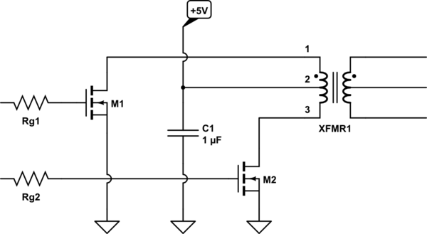
schematic

simulate this circuit – Schematic created using CircuitLab

The center-tapped transformer will be driven by two MOSFETs, whose gates will be controlled by an external chip at about 500 kHz.

  1. Should I add snubber networks (e.g. RC-series)?
  2. Where should those be placed (in parallel to each MOSFET or in parallel with terminals 1 - 3 of the transformer)?

The question arises because all the low-power designs I've seen and used (e.g. Texas Instruments SN6505B) show no snubber networks in their schematics, but as far as I know there is always a leakage inductance of the transformer that should be discharged by a snubber network during MOSFET opening.

\$\endgroup\$
2
  • \$\begingroup\$ First off, back up and ask yourself if you need a snubber. If yes, why? Then one could go on to design one. \$\endgroup\$
    – winny
    Commented Oct 25, 2021 at 10:22
  • \$\begingroup\$ Uhm... I was expecting something like "the circuit is so low power that no snubber is usually required because the leakage inductance is so slow that some other effect can avoid overvoltages" or a similar answer ;) \$\endgroup\$ Commented Oct 25, 2021 at 20:08

1 Answer 1

2
\$\begingroup\$

The SN5605B part is a transformer driver. It is made to drive transformers.

If it would require snubbers under intended operation, it would be stated in the datasheet and shown in the typical application schematics.

The datasheet also shows typical switching waveforms for D1 and D2, which show no spikes.

The part also has slew rate control for the outputs which minimizes EMI.

So it is a part designed not to need a snubber.

\$\endgroup\$
2
  • \$\begingroup\$ It's clear. So the question is why the SN6505B doesn't require a snubber? Maybe because its slew-rate control smoothly discharges the leakage inductance without any overvoltage? \$\endgroup\$ Commented Oct 25, 2021 at 20:06
  • 2
    \$\begingroup\$ That might be one reason. However TI appnote SLLA566A (made in 2018 and updated in 2021) says that while push-pull topologies have inherently low emissions due to their symmetry, the emissions can be even further reduced by using RC snubbers from D1 and D2 pins to ground, if there is a need to do so. \$\endgroup\$
    – Justme
    Commented Oct 25, 2021 at 20:23

Your Answer

By clicking “Post Your Answer”, you agree to our terms of service and acknowledge you have read our privacy policy.

Not the answer you're looking for? Browse other questions tagged or ask your own question.