4
\$\begingroup\$

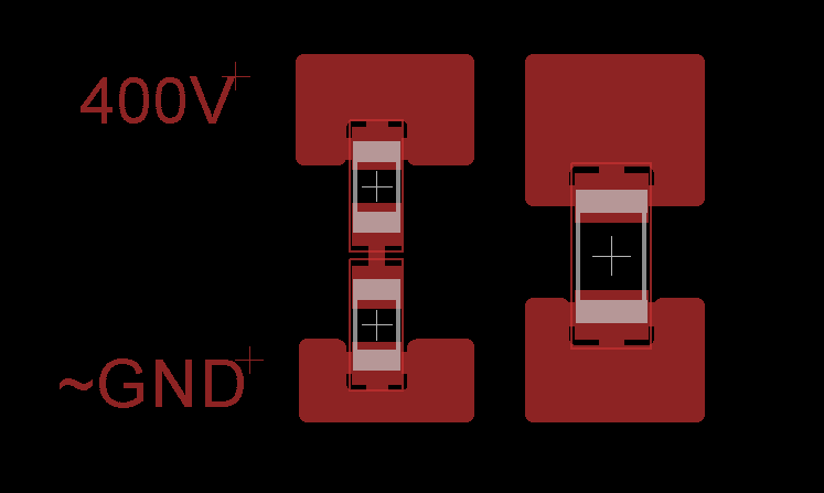
Looking for the smallest & most reliable method of dropping 360V down to ~1V for a PMIC feedback pin. Reliability is probably the most important variable here.

Question:

In general are we be better off with two 1206 resistors in series OR 1 high voltage rated 2010 resistor? Note - I'm not concerned about safety, just reliability.

The given creepage distance is approximately the same based on footprints. In either case, a failure of a single resistor will ruin the product.

My thought:

A single high voltage resistor may be better, given a spot of pollution/dust across the large resistor will have a smaller probability of causing a breakdown given the same size spot on one of the smaller resistors since the spot to creepage distance ratio is smaller on the single larger resistor.

System:

  • Sealed system, internally generates a high voltage (360V DC).) As such no UL type creepage/clearence requirements needed.
  • PMIC generates 360V, ~50W. System has over-current limit, etc.
  • Failure of feedback network will not be a safety issue, just a reliability issue.
  • Medium cost manufacturing in China, but no board pollution IPC specification.
  • The high voltage is not from line voltages. This is a secondary voltage generated from 24V.

enter image description here

\$\endgroup\$
8
  • 1
    \$\begingroup\$ I would derate Voltage 50% and might use 805's with a silicone coating. Dust + humidity reasons. \$\endgroup\$
    – D.A.S.
    Commented Oct 31, 2021 at 17:51
  • 4
    \$\begingroup\$ Are you familiar with dendrites??? With such high electric field strengths, even a little bit of humidity in the air may cause these to short-circuit over time. At a minimum, a good thick conformal coating should be applied. Personally, because I'm extremely risk-averse, I'd use 3 or 4 0805 or 1206 resistors in series. In production we've had trouble with dendrites on 5VDC rails. It's the not absolute voltage, it's the electric field strength that matters most ... V/m $$$$ electronics.stackexchange.com/questions/194020/… \$\endgroup\$
    – Kyle B
    Commented Oct 31, 2021 at 18:10
  • \$\begingroup\$ Bad example ^^^^ My edit didn't take and now it's too late. Much better example: en.wikipedia.org/wiki/Electrochemical_migration \$\endgroup\$
    – Kyle B
    Commented Oct 31, 2021 at 18:44
  • \$\begingroup\$ @KyleB - 3x 805 packages would still have the approximate same V/m as 2x 1206 or 1x 2010.... But yes, I have been thinking conformal coating is needed, then a single HV resistor might be best. \$\endgroup\$
    – MadHatter
    Commented Oct 31, 2021 at 21:09
  • 1
    \$\begingroup\$ Any advice on silicone versus acrylic conformal coating for this specific situation? \$\endgroup\$
    – MadHatter
    Commented Oct 31, 2021 at 23:14

2 Answers 2

1
\$\begingroup\$

Well, if you're discounting safety standards, you can do whatever you like. As for reliability, whether you can find data for typical PCB layouts / spacings / components, or are willing to undertake the effort to produce it yourself for your specific design with expected variations (such as given), that seems like a long shot, expensive, or both.

With respect to safety standards, the first is worse, because it fails under SPOF (single point of failure), i.e. if one resistor fails shorted, the remaining clearance is insufficient. Three or more would be suggested, then. A standard like IEC 60950-1 (with which I am somewhat familiar, though it's now deprecated) still gives creepage and clearance for functional, secondary / non-transient voltage conditions.

With respect to practice, 3 x 0805 chip in series is commonly applied for across-line or transient-limited (by SPD) conditions.

Beyond that, I would be more concerned about component reliability itself (e.g., thin film susceptibility to corrosion, especially sulfurous gasses?), and mitigation such as conformal coating or potting.

\$\endgroup\$
0
\$\begingroup\$

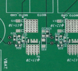
Use two big resistors with a transistor. If the first one fails, the second one will be activated. Consider using PCB via holes for heat dissipation (like below.)

enter image description here

\$\endgroup\$
1
  • 2
    \$\begingroup\$ Your answer could be improved with additional supporting information. Please edit to add further details, such as citations or documentation, so that others can confirm that your answer is correct. You can find more information on how to write good answers in the help center. \$\endgroup\$
    – Community Bot
    Commented Oct 18, 2022 at 13:07

Your Answer

By clicking “Post Your Answer”, you agree to our terms of service and acknowledge you have read our privacy policy.

Not the answer you're looking for? Browse other questions tagged or ask your own question.