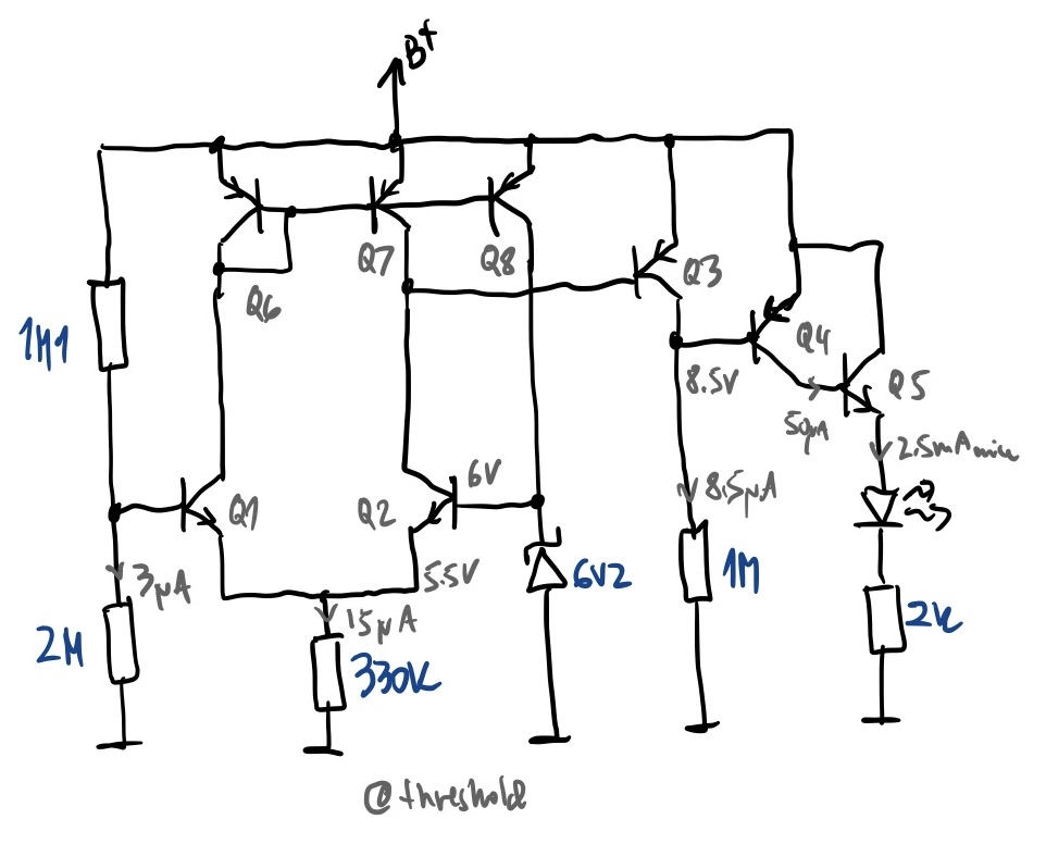
The answer was actually in the first comment by @tobalt, "For sharper switching your need higher open loop gain than a single transistor.", which you can in this case implement with transistors, as I was able to do in this case. But I'm not a professional, so I would like comments from professionals regarding things I didn't think about, or complications regarding to doing it this way. But I also haven't seen this construct around, which makes me also a little extra cautious. But here goes.
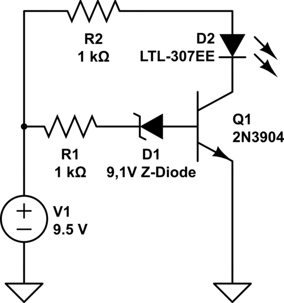
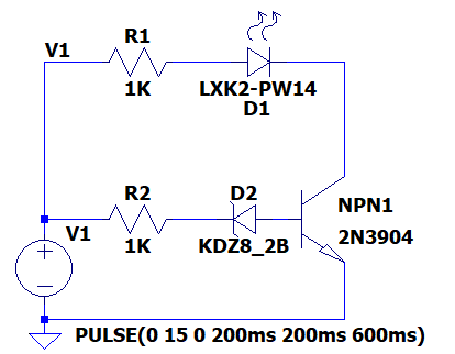
I was able to simulate in LTSpice a solution to your problem, as shown below. Both circuits were on the same schematic, had the same rate of rise in voltage, and therefore are directly comparable. First your circuit for comparison:
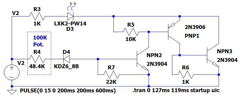
Here is how I minimally modified your circuit to achieve your goals:
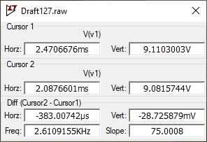
Here is the trace from running this in LTSpice. You should see the trace of your circuit in green, and the trace of my circuit in blue, with the voltage trace in red. Note how gradual the green trace is, and how steep the blue trace is:
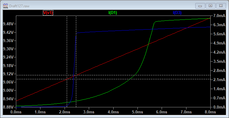
As the two cross-hairs show, at 9.1 volts, it turns fully on in less than 30mV:
So the secret to this circuit is something like a comparator implemented by a three-transistor construct similar to a complementary Darlington, but powered from the rails instead of directly above or below. Each NPN has a pull-down on the base, and each PNP has a pull-up on the base. Neglecting those allows leakage current from the Zener to turn on the "comparator" too early. When the smallest current succeeds in getting into NPN2, the LED turns fully on. It starts turning on around 200nA, and is fully on by 300nA.
Putting a potentiometer at R4 should allow you to calibrate it to work at exactly the voltage around 9.1 V that you want (within reason). If you want it to be permanent, use a 20-turn potentiometer, calibrate it, and add a bit of Loctite, nail-polish, or hot-melt glue to lock it in place.
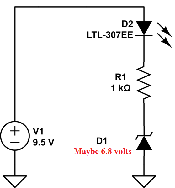
It actually works out well that a 6.8 volt Zener is used, because that voltage has been proven to be relatively temperature-stable, which increases the stability of your circuit. The potentiometer is not temperature-stable, though.
Transistor beta is not a reliable parameter, but that is not a factor in this design because the total gain is something like 1,000,000 (one million!), and it doesn't really matter if the real gain turns out to be 900K or 1.1Meg - the calibration will easily adjust for that. Let us know if you build it!
Here's the source code for the file:
Version 4
SHEET 1 2280 772
WIRE -32 16 -48 16
WIRE 16 16 -32 16
WIRE 160 16 96 16
WIRE 288 16 224 16
WIRE 496 16 480 16
WIRE 544 16 496 16
WIRE 688 16 624 16
WIRE 896 16 752 16
WIRE 1168 16 896 16
WIRE 1328 16 1168 16
WIRE 1168 32 1168 16
WIRE 896 80 896 16
WIRE 928 80 896 80
WIRE 1040 80 1008 80
WIRE 1104 80 1040 80
WIRE 1328 128 1328 16
WIRE 288 144 288 16
WIRE 1040 144 1040 80
WIRE 1168 176 1168 128
WIRE 1168 176 1136 176
WIRE 1264 176 1168 176
WIRE -48 192 -48 16
WIRE 16 192 -48 192
WIRE 144 192 96 192
WIRE 224 192 208 192
WIRE 480 192 480 16
WIRE 544 192 480 192
WIRE 672 192 624 192
WIRE 832 192 736 192
WIRE 976 192 832 192
WIRE -48 208 -48 192
WIRE 480 208 480 192
WIRE 832 256 832 192
WIRE 848 256 832 256
WIRE 1040 256 1040 240
WIRE 1040 256 928 256
WIRE 1136 256 1136 176
WIRE 1152 256 1136 256
WIRE 1328 256 1328 224
WIRE 1328 256 1232 256
WIRE -48 304 -48 288
WIRE 288 304 288 240
WIRE 288 304 -48 304
WIRE 480 304 480 288
WIRE 1040 304 1040 256
WIRE 1040 304 480 304
WIRE 1328 304 1328 256
WIRE 1328 304 1040 304
WIRE -48 320 -48 304
WIRE 480 320 480 304
FLAG -48 320 0
FLAG -32 16 V1
FLAG 480 320 0
FLAG 496 16 V2
SYMBOL npn 224 144 R0
SYMATTR InstName NPN1
SYMATTR Value 2N3904
SYMBOL LED 160 32 R270
WINDOW 0 -50 31 VTop 2
WINDOW 3 0 32 VBottom 2
SYMATTR InstName D1
SYMATTR Value LXK2-PW14
SYMATTR Description Diode
SYMATTR Type diode
SYMBOL zener 208 176 R90
WINDOW 0 0 32 VBottom 2
WINDOW 3 32 32 VTop 2
SYMATTR InstName D2
SYMATTR Value KDZ8_2B
SYMATTR Description Diode
SYMATTR Type diode
SYMBOL res 0 32 R270
WINDOW 0 32 56 VTop 2
WINDOW 3 0 56 VBottom 2
SYMATTR InstName R1
SYMATTR Value 1K
SYMBOL res 0 208 R270
WINDOW 0 32 56 VTop 2
WINDOW 3 0 56 VBottom 2
SYMATTR InstName R2
SYMATTR Value 1K
SYMBOL voltage -48 192 R0
WINDOW 3 34 129 Left 2
WINDOW 123 0 0 Left 0
WINDOW 39 0 0 Left 0
SYMATTR InstName V1
SYMATTR Value PULSE(0 15 0 200ms 200ms 600ms)
SYMBOL npn 976 144 R0
SYMATTR InstName NPN2
SYMATTR Value 2N3904
SYMBOL voltage 480 192 R0
WINDOW 3 34 129 Left 2
WINDOW 123 0 0 Left 0
WINDOW 39 0 0 Left 0
SYMATTR InstName V2
SYMATTR Value PULSE(0 15 0 200ms 200ms 600ms)
SYMBOL zener 736 176 R90
WINDOW 0 0 32 VBottom 2
WINDOW 3 32 32 VTop 2
SYMATTR InstName D4
SYMATTR Value KDZ6_8B
SYMATTR Description Diode
SYMATTR Type diode
SYMBOL res 528 32 R270
WINDOW 0 32 56 VTop 2
WINDOW 3 0 56 VBottom 2
SYMATTR InstName R3
SYMATTR Value 1K
SYMBOL res 528 208 R270
WINDOW 0 32 56 VTop 2
WINDOW 3 0 56 VBottom 2
SYMATTR InstName R4
SYMATTR Value 48.4K
SYMBOL npn 1264 128 R0
SYMATTR InstName NPN3
SYMATTR Value 2N3904
SYMBOL pnp 1104 128 M180
SYMATTR InstName PNP1
SYMATTR Value 2N3906
SYMBOL res 912 96 R270
WINDOW 0 32 56 VTop 2
WINDOW 3 0 56 VBottom 2
SYMATTR InstName R5
SYMATTR Value 10K
SYMBOL res 1136 272 R270
WINDOW 0 32 56 VTop 2
WINDOW 3 0 56 VBottom 2
SYMATTR InstName R6
SYMATTR Value 1K
SYMBOL res 832 272 R270
WINDOW 0 32 56 VTop 2
WINDOW 3 0 56 VBottom 2
SYMATTR InstName R7
SYMATTR Value 22K
SYMBOL LED 688 32 R270
WINDOW 0 -50 31 VTop 2
WINDOW 3 0 32 VBottom 2
SYMATTR InstName D3
SYMATTR Value LXK2-PW14
SYMATTR Description Diode
SYMATTR Type diode
TEXT 974 320 Left 2 !.tran 0 127ms 119ms startup uic
TEXT 568 104 Left 2 ;100K\nPot.
RECTANGLE Normal 640 256 544 80 2
