5
\$\begingroup\$

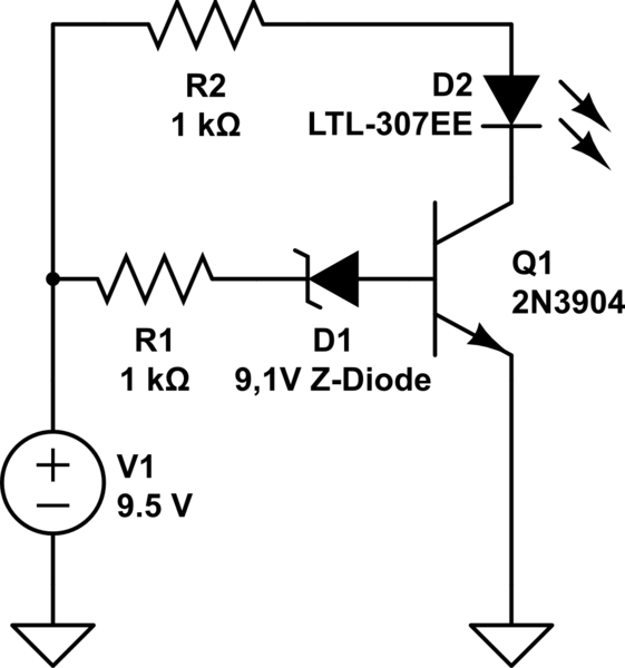
I'm trying to build a 9V battery tester with Zener diodes. I am doing tests with an adjustable power supply.

With a 3904 transistor to do the switching it works ok, but the LED is fading on too slowly.

In this schematic it starts glowing at 9.2V and is fully on at about 10V.

How would I achieve a sharper switching, like the LED is fully lit at 9.2V and fully off at 9.1V?

The 3904 already has a high gain, but maybe I can use a different transistor to achieve this?

schematic

simulate this circuit – Schematic created using CircuitLab

\$\endgroup\$
6
  • 1
    \$\begingroup\$ For sharper switching your need higher open loop gain than a single transistor. Comparators and op amps would be such options, but it depends what else are requirements. \$\endgroup\$
    – tobalt
    Commented Dec 23, 2021 at 12:01
  • 1
    \$\begingroup\$ theerrormagnet, What I do is use a BJT circuit to make a relaxation oscillator. The rate of flashing an LED tells me the voltage. It's quite useful. \$\endgroup\$
    – jonk
    Commented Dec 23, 2021 at 18:38
  • \$\begingroup\$ @jonk - Would you be okay to share your circuit? If I make a question tailored for your answer? \$\endgroup\$ Commented Feb 21, 2022 at 21:13
  • 1
    \$\begingroup\$ @MicroservicesOnDDD You can read about the idea here. (Though I think R7 was a trial idea that I don't think makes much sense and I'd likely just short it out, now.) Depending on your need, I'd redesign the positive feedback and the other resistor values, though. \$\endgroup\$
    – jonk
    Commented Feb 21, 2022 at 21:42
  • \$\begingroup\$ @MicroservicesOnDDD I forgot to point out that the 6N137 isn't needed. You can just use an LED there. In fact, that's how I did it originally. Just wanted a pulsing LED. The 6N137 there is for opto-isolation, in case that's wanted. \$\endgroup\$
    – jonk
    Commented Feb 22, 2022 at 5:08

4 Answers 4

2
\$\begingroup\$

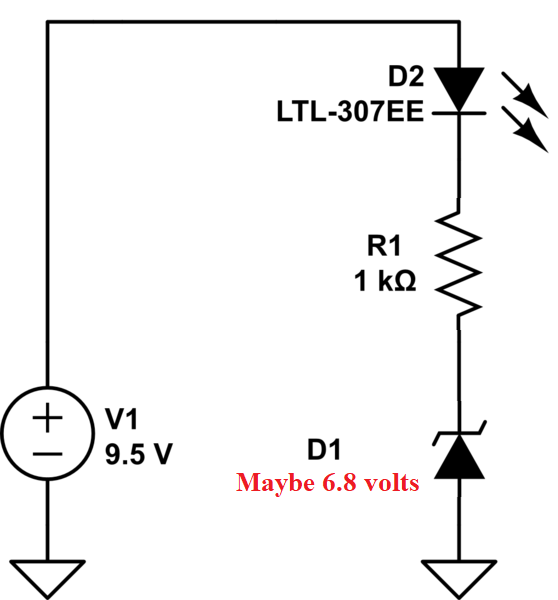
It seems you are going to more trouble than its worth using a BJT. Why not try something like this instead: -

enter image description here

You may need to make the zener voltage 6.8 volts to get the same activation point and, it will be equally "sloppy" in fading-on rather than having a clear-cut on/off transition but, that's to be expected with imprecise components like Zeners and BJTs.

How would I achieve a sharper switching, like the led is fully lit at 9.2V and fully off at 9.1V?

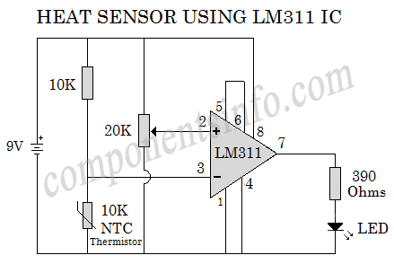
If you want a better circuit you should use a comparator and voltage reference. The gain of the transistor has nothing to do with how your current circuit differentiated between on and off. Maybe use a comparator like the LM311: -

enter image description here

Image from here.

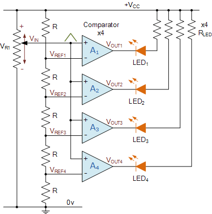
If you replace the NTC thermistor with a precision shunt voltage reference (many to choose from) and set the pot to the "trigger-point" of 9.15 volts then it should be very sharp in response. You can even use multiple comparators to get a "several" level deep LED response: -

enter image description here

Image from here.

\$\endgroup\$
7
  • \$\begingroup\$ Your circuit will not work as the Z-diode has a voltage drop of 9.1V and there will be not enough voltage for the LED. I tried similar circuits, but the problem is that in the end I will be using 3 LEDs and it is much cleaner with a BJT as a switch as the LEDs will have a more equal power. \$\endgroup\$ Commented Dec 23, 2021 at 11:22
  • \$\begingroup\$ @theerrormagnet true so I shall reduce the zener voltage. \$\endgroup\$
    – Andy aka
    Commented Dec 23, 2021 at 11:23
  • \$\begingroup\$ The idea with the LM311 is good. I will look into this IC. But I usually like to work with analog discrete components. It should be possible to do this somehow, you probably would need some form of transistor logic, but I have no clue how to do it at the moment. \$\endgroup\$ Commented Dec 23, 2021 at 11:47
  • 2
    \$\begingroup\$ No, forget it. Take my word for it. If you are using a zener as a voltage detector then it will be sloppy. Of course you could use two BJTs wired as a differential pair with a zener voltage reference on one input and the voltage sensing on the other input but, then you are half way to a comparator and, it still won't be as good as just buying a comparator because you'd probably need to add at least two more BJTs to get the interface to the LED working. \$\endgroup\$
    – Andy aka
    Commented Dec 23, 2021 at 12:10
  • 1
    \$\begingroup\$ Your circuit is simple and will work .I have used a constant current source for R1 and sometimes used a diac for the zener to make things snappy , \$\endgroup\$
    – Autistic
    Commented Dec 24, 2021 at 7:10
1
\$\begingroup\$

If you do want stay with the BJR circuit, then you can get a sharper transition by:

  1. Add a R across the B-E of Q1 -- use 500 Ω (470 is available) . Now even small leakage in the zener won't directly turn on Q1 until it exceeds 0.6V/470Ω. You'll need to reduce the zener BV. For a 9.1V threshold and 1k, 470 Ω resistors, you'd need a zener of about 9.1-3*0.7 = 12 V.

  2. You can get a slightly sharper transition by also putting a resistor in parallel with the LED -- 10 kΩ is suitable.

\$\endgroup\$
1
\$\begingroup\$

If you really want to copy the schematic of a front-end of a comparator…

For the circuit to be practical - since it’s battery powered - it should be micro power until the LED comes on. So you’ll need quite a bit of gain.

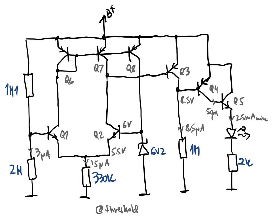
I haven’t tried it, but imagine that the circuit below would work or be a good starting point. The ratio of the resistive divider feeding the base of Q1 will require adjustment for sure. The circuit should consume <30uA at room temperature when idle (i.e. the LED is off), so it won’t be killing batteries. The transistors can be general purpose small signal types, e.g. 2N2222 and 2N2907, ZTX455 and ZTX555, etc.

For extra credit, and a few more transistors, the Zener voltage could be used to stabilize the LED current, so at voltages above threshold, the brightness of the LED would be kept constant.

The schematic of a battery voltage indicator

Q1-Q2 are a long-tailed pair fed by the Q6-Q7 current mirror. Q8 is a current source for the Zener. Q3-Q5 are gain stages for the LED.

I’m sure the room-temperature idle current could be lowered even further, but assembly would require extreme cleanliness - i.e. all flux would need to be washed off, and solderless breadboards and assembly with ungloved hands would not work all that great. Micro power solutions work great when integrated inside an IC, where contamination is controlled in the fab, and not on the bench where the IC may be put to use. In a bipolar IC, this could probably be made to consume 1-2uA at room temperature max, using a current sink as a load for the differential pair.

If I had to make a practical battery level detector circuit, I’d just use some micro power comparator with a built-in reference in a tiny package that consumes 1uA or less. Say LTC1540.

Now, perhaps you don’t care about the circuit being micro power. In that case a push button “battery check” and any off-the-shelf integrated comparator+reference are plenty enough. Probably a TLV431 set up as a comparator, with LM334 as a current source to set the LED current, would do the job admirably and still below 100uA when the LED is off. It’ll look like a discrete circuit, since both are 3-terminal devices :)

A good variant on the micro power theme would be a micro power flasher that flashes a red/green LED, with green indicating good battery, and red indicating need for replacement. Such circuits can have a very respectably low average current if you keep the LED flashes short and spaced apart. And it’s lots of fun to design them from simple functional blocks with a bit more functionality than a discrete transistor.

3-terminal current sources and shunt regulators/comparators are extremely versatile building blocks, so if you have a bunch of them in your “handy parts bin”, they can go a long way in solving common problems without a need for more specialized parts. That’s especially true with component shortages: the jellybean parts are available just fine, from multiple sources. They take more effort to get going if you’re not familiar with the “idioms” used in such designs. That’s why I recommend old NatSemi and Linear Technology app notes. They are full of inspiration for such circuits.

\$\endgroup\$
1
  • 1
    \$\begingroup\$ Very cool! It's nice to see someone showing a microcurrent / micropower design. I've read the relevant section in Art of Electronics, and read my Current Sources book, but still have to branch out that way, so thanks also for the practical advice to keep those jellybeans in my box -- if they were there, I would have already been using them, I'm sure. Nice answer, so thanks. \$\endgroup\$ Commented Feb 23, 2022 at 6:32
0
\$\begingroup\$

The answer was actually in the first comment by @tobalt, "For sharper switching your need higher open loop gain than a single transistor.", which you can in this case implement with transistors, as I was able to do in this case. But I'm not a professional, so I would like comments from professionals regarding things I didn't think about, or complications regarding to doing it this way. But I also haven't seen this construct around, which makes me also a little extra cautious. But here goes.

I was able to simulate in LTSpice a solution to your problem, as shown below. Both circuits were on the same schematic, had the same rate of rise in voltage, and therefore are directly comparable. First your circuit for comparison:
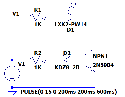
enter image description here

Here is how I minimally modified your circuit to achieve your goals: enter image description here
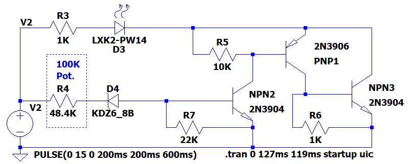
Here is the trace from running this in LTSpice. You should see the trace of your circuit in green, and the trace of my circuit in blue, with the voltage trace in red. Note how gradual the green trace is, and how steep the blue trace is:
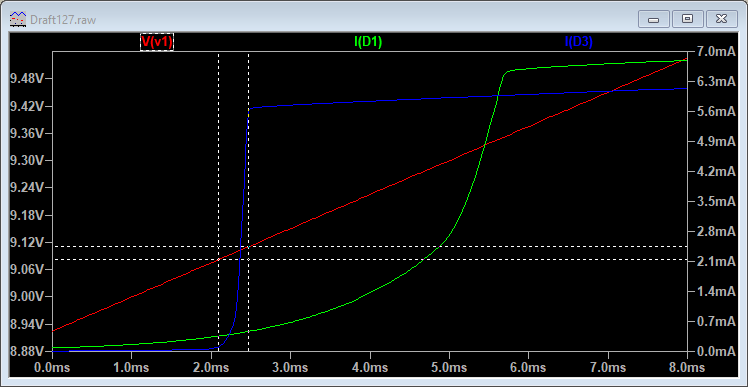
enter image description here

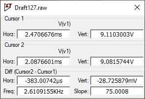
As the two cross-hairs show, at 9.1 volts, it turns fully on in less than 30mV:
enter image description here

So the secret to this circuit is something like a comparator implemented by a three-transistor construct similar to a complementary Darlington, but powered from the rails instead of directly above or below. Each NPN has a pull-down on the base, and each PNP has a pull-up on the base. Neglecting those allows leakage current from the Zener to turn on the "comparator" too early. When the smallest current succeeds in getting into NPN2, the LED turns fully on. It starts turning on around 200nA, and is fully on by 300nA.

Putting a potentiometer at R4 should allow you to calibrate it to work at exactly the voltage around 9.1 V that you want (within reason). If you want it to be permanent, use a 20-turn potentiometer, calibrate it, and add a bit of Loctite, nail-polish, or hot-melt glue to lock it in place.

It actually works out well that a 6.8 volt Zener is used, because that voltage has been proven to be relatively temperature-stable, which increases the stability of your circuit. The potentiometer is not temperature-stable, though.

Transistor beta is not a reliable parameter, but that is not a factor in this design because the total gain is something like 1,000,000 (one million!), and it doesn't really matter if the real gain turns out to be 900K or 1.1Meg - the calibration will easily adjust for that. Let us know if you build it!

Here's the source code for the file:

Version 4
SHEET 1 2280 772
WIRE -32 16 -48 16
WIRE 16 16 -32 16
WIRE 160 16 96 16
WIRE 288 16 224 16
WIRE 496 16 480 16
WIRE 544 16 496 16
WIRE 688 16 624 16
WIRE 896 16 752 16
WIRE 1168 16 896 16
WIRE 1328 16 1168 16
WIRE 1168 32 1168 16
WIRE 896 80 896 16
WIRE 928 80 896 80
WIRE 1040 80 1008 80
WIRE 1104 80 1040 80
WIRE 1328 128 1328 16
WIRE 288 144 288 16
WIRE 1040 144 1040 80
WIRE 1168 176 1168 128
WIRE 1168 176 1136 176
WIRE 1264 176 1168 176
WIRE -48 192 -48 16
WIRE 16 192 -48 192
WIRE 144 192 96 192
WIRE 224 192 208 192
WIRE 480 192 480 16
WIRE 544 192 480 192
WIRE 672 192 624 192
WIRE 832 192 736 192
WIRE 976 192 832 192
WIRE -48 208 -48 192
WIRE 480 208 480 192
WIRE 832 256 832 192
WIRE 848 256 832 256
WIRE 1040 256 1040 240
WIRE 1040 256 928 256
WIRE 1136 256 1136 176
WIRE 1152 256 1136 256
WIRE 1328 256 1328 224
WIRE 1328 256 1232 256
WIRE -48 304 -48 288
WIRE 288 304 288 240
WIRE 288 304 -48 304
WIRE 480 304 480 288
WIRE 1040 304 1040 256
WIRE 1040 304 480 304
WIRE 1328 304 1328 256
WIRE 1328 304 1040 304
WIRE -48 320 -48 304
WIRE 480 320 480 304
FLAG -48 320 0
FLAG -32 16 V1
FLAG 480 320 0
FLAG 496 16 V2
SYMBOL npn 224 144 R0
SYMATTR InstName NPN1
SYMATTR Value 2N3904
SYMBOL LED 160 32 R270
WINDOW 0 -50 31 VTop 2
WINDOW 3 0 32 VBottom 2
SYMATTR InstName D1
SYMATTR Value LXK2-PW14
SYMATTR Description Diode
SYMATTR Type diode
SYMBOL zener 208 176 R90
WINDOW 0 0 32 VBottom 2
WINDOW 3 32 32 VTop 2
SYMATTR InstName D2
SYMATTR Value KDZ8_2B
SYMATTR Description Diode
SYMATTR Type diode
SYMBOL res 0 32 R270
WINDOW 0 32 56 VTop 2
WINDOW 3 0 56 VBottom 2
SYMATTR InstName R1
SYMATTR Value 1K
SYMBOL res 0 208 R270
WINDOW 0 32 56 VTop 2
WINDOW 3 0 56 VBottom 2
SYMATTR InstName R2
SYMATTR Value 1K
SYMBOL voltage -48 192 R0
WINDOW 3 34 129 Left 2
WINDOW 123 0 0 Left 0
WINDOW 39 0 0 Left 0
SYMATTR InstName V1
SYMATTR Value PULSE(0 15 0 200ms 200ms 600ms)
SYMBOL npn 976 144 R0
SYMATTR InstName NPN2
SYMATTR Value 2N3904
SYMBOL voltage 480 192 R0
WINDOW 3 34 129 Left 2
WINDOW 123 0 0 Left 0
WINDOW 39 0 0 Left 0
SYMATTR InstName V2
SYMATTR Value PULSE(0 15 0 200ms 200ms 600ms)
SYMBOL zener 736 176 R90
WINDOW 0 0 32 VBottom 2
WINDOW 3 32 32 VTop 2
SYMATTR InstName D4
SYMATTR Value KDZ6_8B
SYMATTR Description Diode
SYMATTR Type diode
SYMBOL res 528 32 R270
WINDOW 0 32 56 VTop 2
WINDOW 3 0 56 VBottom 2
SYMATTR InstName R3
SYMATTR Value 1K
SYMBOL res 528 208 R270
WINDOW 0 32 56 VTop 2
WINDOW 3 0 56 VBottom 2
SYMATTR InstName R4
SYMATTR Value 48.4K
SYMBOL npn 1264 128 R0
SYMATTR InstName NPN3
SYMATTR Value 2N3904
SYMBOL pnp 1104 128 M180
SYMATTR InstName PNP1
SYMATTR Value 2N3906
SYMBOL res 912 96 R270
WINDOW 0 32 56 VTop 2
WINDOW 3 0 56 VBottom 2
SYMATTR InstName R5
SYMATTR Value 10K
SYMBOL res 1136 272 R270
WINDOW 0 32 56 VTop 2
WINDOW 3 0 56 VBottom 2
SYMATTR InstName R6
SYMATTR Value 1K
SYMBOL res 832 272 R270
WINDOW 0 32 56 VTop 2
WINDOW 3 0 56 VBottom 2
SYMATTR InstName R7
SYMATTR Value 22K
SYMBOL LED 688 32 R270
WINDOW 0 -50 31 VTop 2
WINDOW 3 0 32 VBottom 2
SYMATTR InstName D3
SYMATTR Value LXK2-PW14
SYMATTR Description Diode
SYMATTR Type diode
TEXT 974 320 Left 2 !.tran 0 127ms 119ms startup uic
TEXT 568 104 Left 2 ;100K\nPot.
RECTANGLE Normal 640 256 544 80 2
\$\endgroup\$

Your Answer

By clicking “Post Your Answer”, you agree to our terms of service and acknowledge you have read our privacy policy.

Not the answer you're looking for? Browse other questions tagged or ask your own question.