Well, Chris (@VerbalKint) will probably come in with a perfect answer at some point (as usual!) but in the meantime here's some input.
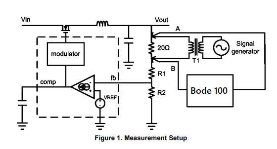
Assuming you are looking at the open-loop response of your converter, which looks like the case from your Bode 100 setup diagram:
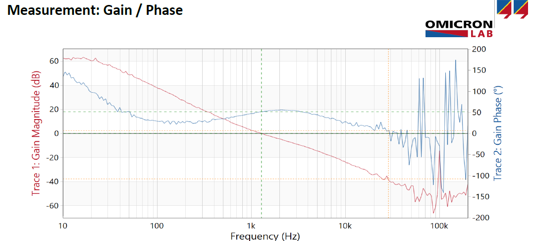
- High gain (60 to 40 dB) at lower frequencies (0 -100 Hz) indicates that very small feedback voltage is needed to keep the power supply output regulated.
Yes. Ideally, you could put a pole at the origin to form an integrator so that you would drive the steady-state DC error to zero. But high gain at DC/low frequency is desirable.
- High phase margin at lower frequency indicates that, feedback voltage's most of the part will be subtracted from Vref ( negative feedback).
Sort of. You have negative feedback, but phase margin is ONLY measured at the point where the gain crosses 0 dB. A system can be perfectly stable (albeit conditionally) if the phase crosses 180 degrees while there is still gain, as long as the phase at the zero dB point is acceptable.
- As frequency increases, it takes higher feedback voltage to keep the power supply output regulated and at 0 dB it requires as much as feedback voltage of output voltage value at the feedback pin for regulation (0 dB = 1 gain = Vout / Vfeedback)
Right, without high loop gain you won't have good disturbance rejection (at the frequencies where the gain is poor). This impacts the transient performance.
- For frequencies beyond crossover, feedback voltage no longer regulate power supply in single cycle but will take a number of cycle to regulates since gain is in fractional number.
What do you mean by cycles? Switching cycles? The number of switching cycles needed to regulate doesn't go from 1 to multiple above the crossover. Again, the crossover frequency will impact transient performance and settling, but it's not specifically linked in most cases to switching cycles. If your loop doesn't have gain you can't expect it to respond to disturbances with frequency content in the region without gain.
- As frequency increases, the feedback signal phase is more going towards 180 degree leading to addition of feedback signal instead subtraction from Vref at the error amplifier (positive feedback).
Well, if you close the loop with sufficient phase margin, you won't have positive feedback. If you do wind up with positive feedback then your supply will be unstable. So the goal is to close the loop before the phase margin goes to zero. Typically the phase will approach the -180 degree point as the frequency increases, but might approach or cross that point and recover by the 0 dB point, and that could still give you a stable system. That's sometimes the case in voltage mode buck converters for example.


