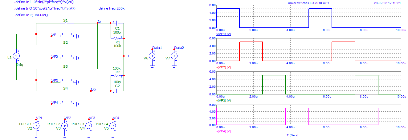
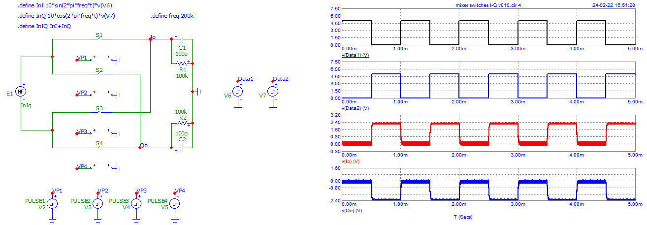
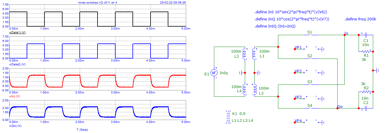
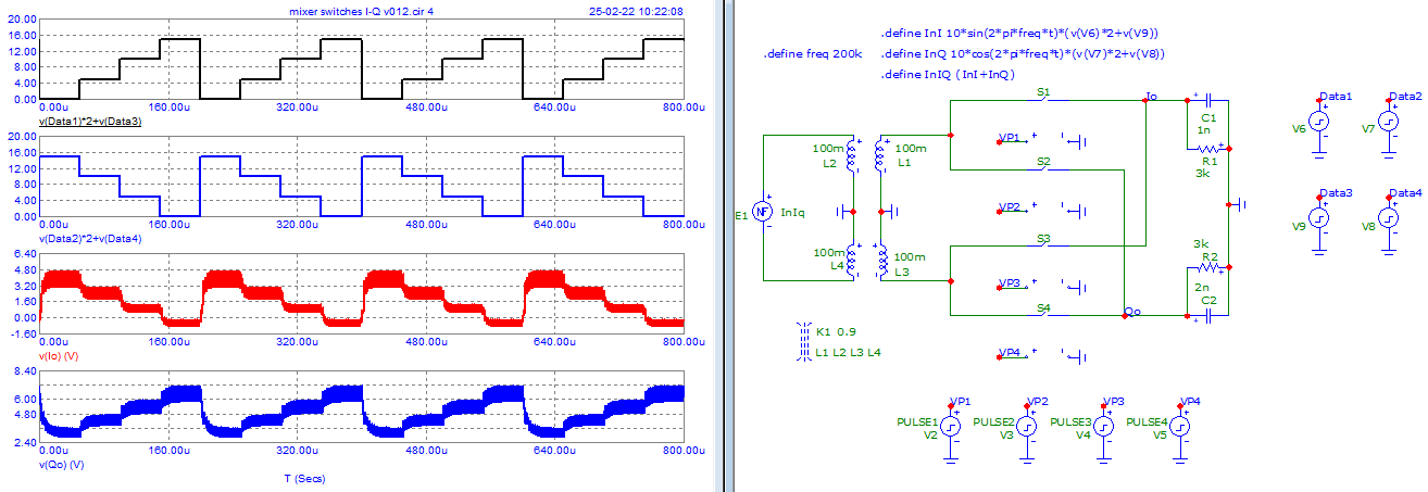
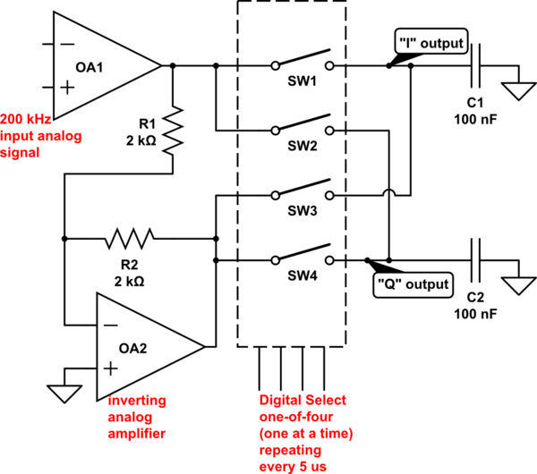
Antonio's suggestion of four switches to make a mixer is an ideal one for low-frequencies like 200 kHz. A local oscillator at 4X frequency (800 kHz) allows I & Q output:
simulate this circuit – Schematic created using CircuitLab
For this example, engage SW1 switch closed, with SW2, SW3, SW4 open-circuit.
- 1.25 microseconds later, open SW1 and close SW2 (SW3, SW4 remain open-circuit).
- 1.25 microseconds later, open SW2 and close SW3. (SW1,SW4 remain open-circuit)
- 1.25 microseconds later, open SW3 and close SW4. (SW1, SW2 remain open-circuit)
- 1.25 microseconds later, open SW4 and close SW1 returning to the first state.
- continue this sequence.
The switch series resistance, combined with C1 and C2 form a RC low-pass filter. The filter's equivalent resistance is 2X switch resistance. I'm assuming op-amps have zero output resistance. You can add some resistance in series with the switches to improve linearity.
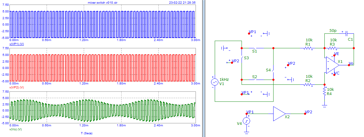
If you don't need I & Q output, this demodulator can be simplified to a SPDT switch, with local oscillator frequency of 200 kHz square wave driving the single select-line. In the LTspice schematic below, the switch control line is unnecessarily complex; two out-of-phase square wave generators.
A single capacitor is now used at switch output. It has the characteristic response of a single-pole low-pass filter having RC time constant of ron*C1.
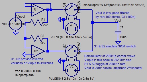
Input to the SPDT switch here is opamp buffers that drive the switches with low resistance voltage waves having opposing (inverted) amplitudes, and identical DC average voltage. In RF mixers, this is often done with a center-tapped transformer.
If CMOS or JFET analog switches are used for SPDT switch, electronic switches may require a DC offset so that peak waveform voltages of their input/output lie within DC supply voltage. Texas instruments describes the analog pre-conditioning in their app-note SBOA096:
https://www.ti.com/lit/an/sboa096/sboa096.pdf?ts=1645727329231&ref_url=https%253A%252F%252Fwww.google.com%252F


