1
\$\begingroup\$

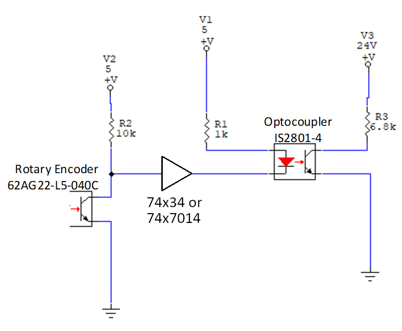
I have this basic circuit but it's doing my head in with the actual prototype: enter image description here
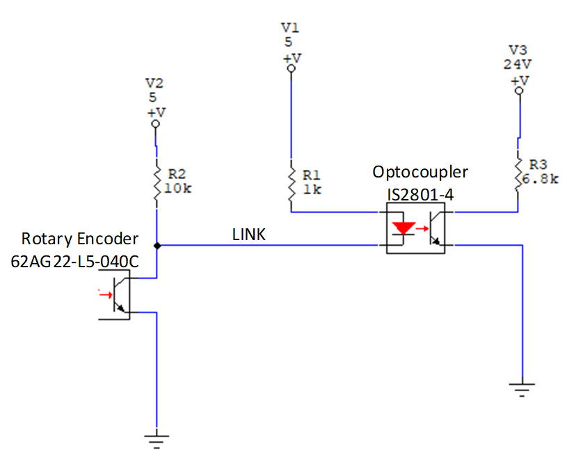
When LINK is open (not connected to the optocoupler), Encoder output works OK - it goes 0V and 5V. Also while LINK is open and if I put optocoupler cathode to ground, optocoupler output is triggered.

But when LINK is connected, output (LINK voltage) just swings between 3.1V and 5V.

3.1V is too high for a LOW logic so optocoupler output isn't triggered. I thought it was a component issue but it's same result for other prototype.

Simulation with LTSpice shows circuit should work. But not in my actual prototype.

Encoder: https://www.grayhill.com/documents/62AG-VG-Datasheet

Opto-isolator: http://isocom.com/wp-content/uploads/2017/09/DD93211-IS2801-4-240317.pdf

Ideas please?

\$\endgroup\$
3
  • \$\begingroup\$ R2 doesn't need to be there at all. The voltage drop across the CE might be too high for the R1 you chose. It's only specified as being no greater than 1V. \$\endgroup\$
    – DKNguyen
    Commented Mar 17, 2022 at 21:49
  • \$\begingroup\$ Hi DKNguyen, I think you're right. I'll remove R2. Encoder should be able to accept 3.8mA from the R1/LED pull-up right? \$\endgroup\$ Commented Mar 17, 2022 at 22:14
  • \$\begingroup\$ Congrats on a well formed question. I’d question if you need the opto coupler at all but the encoder datasheet is sparse on the voltage and current rating of the phototransistor. Saying you can’t add parts is probably not the best strategy - you’ve started with a poor design and you ‘might’ be able to tweak the values but if push comes to shove you’ll have to change the design and add/change parts. It wasn’t a major issue years ago to do this. \$\endgroup\$
    – Kartman
    Commented Mar 17, 2022 at 22:55

5 Answers 5

1
\$\begingroup\$

As @DKNguyen said, the voltage drop on your encoder could be as much as 1 V. So let's assume 1.2V across the LED (typ value). That leaves 2.8 V across the 1 K resistor, meaning your LED current is roughly 2.8 mA.

The CTR (Current Transfer Ratio) of the opto can be as low as 50%. So you could have 1.4 mA in the 6.8K resistor. So your output could swing between 24V and 24 V - 1.4 mA * 6.8K or 14.48 V.

Clearly you need to decrease R1 and/or increase R3. Since you're seeing the encoder having difficulty even reaching the 1 V Vce, decreasing R1 may not be an option. A higher CTR opto or buffer between the output of the encoder and the opto may be necessary if increasing R3 causes the edges to be too slow.

\$\endgroup\$
0
\$\begingroup\$

The encoder's transistor cannot sink enough current to turn on the LED inside the opto, so you're seeing this as a voltage higher than 0V (and incorrect operation.)

Try this:

Add a buffer

Add a "buffer" between them. For 5V, the "x" can be several different things, like HC (for high-speed CMOS), LS (for low-power Schottky), or ALS (advanced LS). These can be sort-of challenging to search for as not all combinations are available. And these series will have different output load capabilities. Variants also include "inverting" types, and types with "open collector" outputs.

I suggest you try something like Octopart to narrow down candidates. Pull up the datasheets for these and make sure that the chosen buffer is:

  1. Non-inverting (or inverting if you can accomidate that.)
  2. Push-pull output. This means the output can both push the line high and low.
  3. Can output enough current to light the LED. This should be at least 15mA, although only about 4mA will flow due to the LED's 1k resistor. (You might have to change that 1k to 470Ω, even 330Ω to get it working well.)

The buffer has very high input impedance, so it will not "load down" the encoder output. And a buffer has low output impedance, so it can effectively drive loads like a LED.

\$\endgroup\$
3
  • \$\begingroup\$ Hi rdtsc, thanks for the comment, much appreciated. unfortunately, PCBs are with me now so can't add another device. Will try to remove R1 and try to tweak R2 value so it works for both encoder and optocoupler. \$\endgroup\$ Commented Mar 17, 2022 at 22:20
  • \$\begingroup\$ @ArielNarboada I don't think this will be possible as the optocoupler needs a lot of current compared to what you can get with the encoder. You can always bodge PCBs, cut traces, solder wires to pads meant for components, etc. I think it wouldn't be too hard here as the "link" wire is already exposed and can be replaced with the buffer or transistor. \$\endgroup\$
    – Miron
    Commented Mar 17, 2022 at 22:28
  • \$\begingroup\$ Hi Miron, the optocoupler is quad type and there are 15 of this. rest of the inputs are coming from a mechanical switch which goes to GND when activated. This works OK at 24V side as it swings between 24V and 0V. Unfortunately, 2 inputs are coming from the encoder (Output A and Output B). \$\endgroup\$ Commented Mar 17, 2022 at 22:36
0
\$\begingroup\$

The output is the collector of a photo-transistor. The datasheet doesn't specify a maximum sink current.

However, I've found that photo-transistors in opto-sensors are often as weak as a kitten. Opto-sensors I used a long time ago couldn't drive a 74LS logic gate input because they couldn't sink the high leakage current of the 74LS.

You should buffer the photo-transistor to drive your LED. The photo-transistor's datasheet defines the following:

  • Vce(LO) <= 1.0 V
  • Vce(HI) >= 2.0 V

These may be conservative values on their part but design around the stated values.

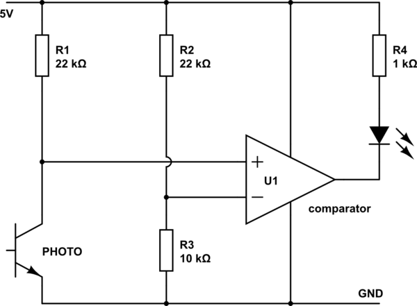
Buffering with a cheap comparator with a strong enough output lets the threshold be easily set. The below circuit has a 1.66 V threshold.

It shows the photo-transistor pulled up to the same 5 V but you can change that to suit. As it happens, this is what I used in for my sensors because it was cheap and a comparator would draw negligible input current.

schematic

simulate this circuit – Schematic created using CircuitLab

\$\endgroup\$
2
  • \$\begingroup\$ A comparator is a bit overkill for this, lots of extra components needed \$\endgroup\$
    – Miron
    Commented Mar 17, 2022 at 22:30
  • \$\begingroup\$ @Miron, nope. Answer gives justification plus previous design exercise. Two resistors is not lots. \$\endgroup\$
    – TonyM
    Commented Mar 17, 2022 at 22:40
0
\$\begingroup\$

schematic

simulate this circuit – Schematic created using CircuitLab

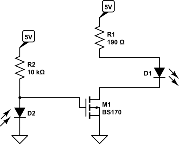
A photodiode/phototransistor can be though of as a current source. The encoder can't sink enough current to power the optocoupler diode, which needs 20mA forward current (the LED series resistor formula will tell you R1 should be 190 ohms, but it seems to be working fine for you). The solution is to have a single transistor to amplify the current. A small NMOS, like the BS170 will do (since you only need 20mA max for the octocoupler), but because of the semiconductor shortage, any will do as long as it has threshold voltage less than 3V. Octopart is good for finding in-stock parts. Common NMOS transistors

\$\endgroup\$
4
  • \$\begingroup\$ Hi Miron, thanks for the comment, much appreciated. unfortunately, PCBs are with me now so can't add another device. Will try to remove R1 and try to tweak R2 value so it works for both encoder and optocoupler. \$\endgroup\$ Commented Mar 17, 2022 at 22:24
  • \$\begingroup\$ Hi Miron, will this do? digikey.com.au/en/products/detail/diodes-incorporated/… \$\endgroup\$ Commented Mar 17, 2022 at 23:17
  • \$\begingroup\$ BS170 Vgs(th) max makes it a 100 ohm switch give or take. so beware of LED current \$\endgroup\$
    – D.A.S.
    Commented Mar 17, 2022 at 23:59
  • \$\begingroup\$ @ArielNarboada yes, looks ok to me, Vgs, Rds on and Id max are good \$\endgroup\$
    – Miron
    Commented Mar 18, 2022 at 4:20
0
\$\begingroup\$

Problems

  1. Rotary Switch is a weak opto-driver for a 10k pullup to 5V meaning it is only guaranteed to drive 5V/10k=0.5 mA to ground.
  2. You show a design with 2 cascaded Opto-isolators and 3 power supplies, V1,V2,V3 , yet all sharing the same ground which defeats the purpose of the 2nd optoisolator.
  3. The 2nd redundant OptoIsolator is also a weak current driver with CTR=50% min when in the linear range of Vce=5V but drops to about 10%, as a saturated switch ( not clearly shown in datasheet ) .

You don't need another opto-isolator do you?

Solutions

  • There are many methods to boost current gain to logic levels yet the 24V output in not defined as a logic level nor the low-level tolerance.

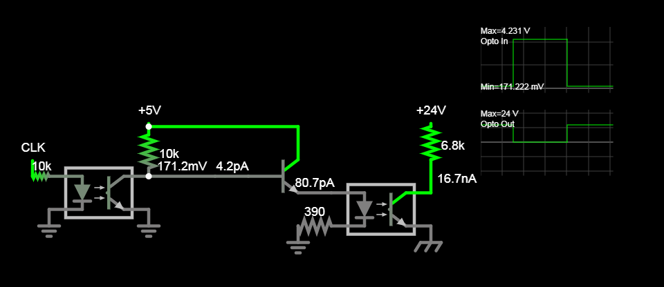
  • The 1st obvious to me is to insert a transistor emitter follower to boost current, but that requires cuts & jumpers.

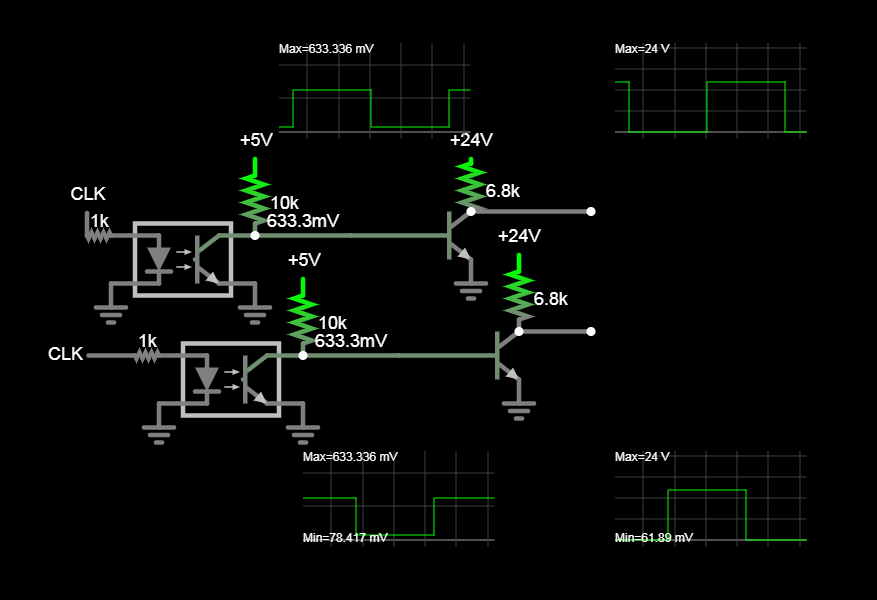
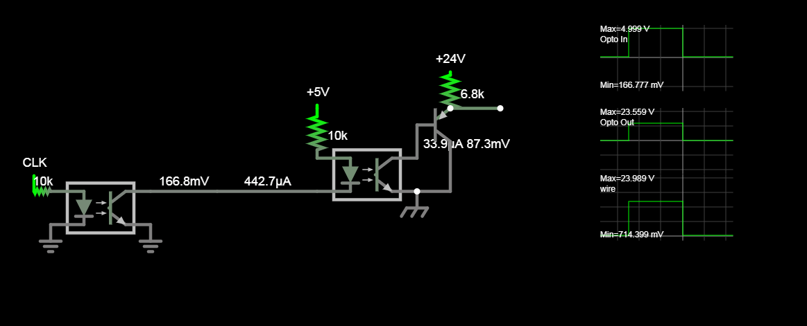
  • The 2nd choice, that I prefer is to replace Opto IS2801-4 with any NPN transistor

Simulated below with quadrature rotary opto encoder.

enter image description here

It is obvious from your drawing that V1 & V2 must share grounds to work, but not V3. So if there is something you haven't specified in the question, now would be a good time to do that.

I can't help but feel your overall goals can be done better, if you gave some clues.

edit > V3 has a separate ground. Thus the need for the optocoupler. – Ariel Narboada 22 min ago

Plan B

  • back to 1st choice and insert NPN and current limiting R with cuts & jumpers.

enter image description here

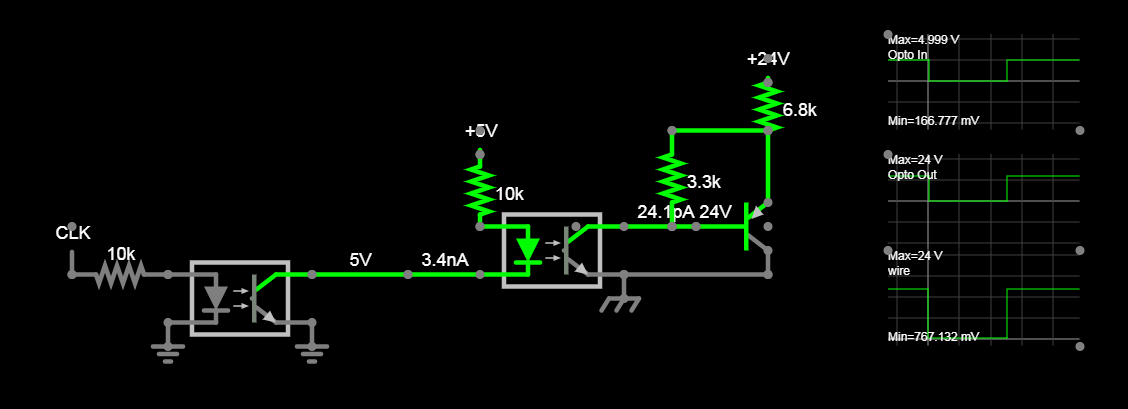
3rd choice

  • Add buffer to output enter image description here

If you need faster risetime. enter image description here

\$\endgroup\$
7
  • \$\begingroup\$ Thanks Tony. V3 has a separate ground. Thus the need for the optocoupler. \$\endgroup\$ Commented Mar 17, 2022 at 23:11
  • \$\begingroup\$ Next time, test your assumptions before layout of PCB. and better, make design specs 1st \$\endgroup\$
    – D.A.S.
    Commented Mar 17, 2022 at 23:36
  • \$\begingroup\$ When you say 'current limiting R', is that the 390ohm resistor in your diagram above? thanks. will now look for this npn. \$\endgroup\$ Commented Mar 17, 2022 at 23:40
  • \$\begingroup\$ Check inverted logic affects \$\endgroup\$
    – D.A.S.
    Commented Mar 17, 2022 at 23:50
  • \$\begingroup\$ logic inversion not an issue. looking now at your proposal and use of a single nmos as suggested by miron. \$\endgroup\$ Commented Mar 17, 2022 at 23:53

Your Answer

By clicking “Post Your Answer”, you agree to our terms of service and acknowledge you have read our privacy policy.

Not the answer you're looking for? Browse other questions tagged or ask your own question.