3
\$\begingroup\$

I recently purchased these cheap digital voltmeters from Amazon to display the output of my 2.5 kV HV supply. The HV supply has a dedicated 1/1000 output (0 - 2.5V)for monitoring, which I am trying to measure using the cheap voltmeter.

The voltmeter has 3 wires: +5V power, GND, and probe. Both the HV supply and voltmeter are powered by a single 5V supply. However, the voltmeter is consistently measuring half the actual value. When I measure the 1/1000 output with a Fluke multimeter (with other voltmeter disconnected) it measures the correct value.

I have tested the digital voltmeter with other benchtop supplies (5V, 12V, 15V) and it seems to work fine. Any suggestions on what I could be missing here?

EDIT: The 1/1000 output shares ground with other HV supply inputs/outputs.

\$\endgroup\$
7
  • \$\begingroup\$ Your Fluke multimeter very likely has a standard 10 MEGohm input resistance. Amazon meter likely has less input resistance - perhaps due to the "calibration" potentiometer. The lower input resistance could cause a low reading compared with the Fluke. \$\endgroup\$
    – glen_geek
    Commented Mar 29, 2022 at 18:31
  • 5
    \$\begingroup\$ What does the Fluke DVM measure when you connect both Fluke and other meter to the HV test point? I suspect that the input resistance of the cheap DVM is much less than that of the Fluke meter, and is loading the HV test point, causing the low reading. \$\endgroup\$ Commented Mar 29, 2022 at 18:31
  • 1
    \$\begingroup\$ @PeterBennett With other meter connected, the Fluke measures half value as well. \$\endgroup\$
    – earl
    Commented Mar 29, 2022 at 18:32
  • \$\begingroup\$ What to check for when buying an electronic component or module \$\endgroup\$
    – Andy aka
    Commented Mar 29, 2022 at 18:41
  • 1
    \$\begingroup\$ @All - FYI some comments were deleted here, after being flagged by other site members (or they were deleted because they made no sense, as they replied to now-deleted comments). Remember that condescending comments are not allowed and they count towards possible future suspensions. Don't write comments that poke fun at someone or at their actions. Thanks. \$\endgroup\$
    – SamGibson
    Commented Mar 29, 2022 at 18:45

2 Answers 2

7
\$\begingroup\$

The input impedance of those modules is in the 100K range- they use a divider directly into the ADC input of a microcontroller, as opposed to multimeters which are 10M\$\Omega\$ down to maybe 1M\$\Omega\$ for some cheap handheld meters. Since it reads about half, that implies the output resistance of the HV unit is also around 100K\$\Omega\$ and you need a 10M\$\Omega\$ or higher input resistance to get an accurate reading.

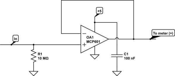
You can either buffer the input with an op-amp or you can get a meter module that has a 10M\$\Omega\$ input resistance.

Eg. MCP601

schematic

simulate this circuit – Schematic created using CircuitLab

\$\endgroup\$
1
  • 1
    \$\begingroup\$ I tried buffering with a TL072 that I had lying around, and that seems to have done it. Thank you! \$\endgroup\$
    – earl
    Commented Mar 31, 2022 at 13:38
4
\$\begingroup\$

You need to know more about the 1/1000 output (0 - 2.5V)for monitoring. Is it a resistive voltage divider and what resistors are used?

What is the input resistance of the Fluke multimeter and what of the cheap voltmeter?

The input resistance of the cheap voltmeter is too low, the load for the monitor output is too much and that is why the measured voltage is too low.

\$\endgroup\$

Your Answer

By clicking “Post Your Answer”, you agree to our terms of service and acknowledge you have read our privacy policy.

Not the answer you're looking for? Browse other questions tagged or ask your own question.