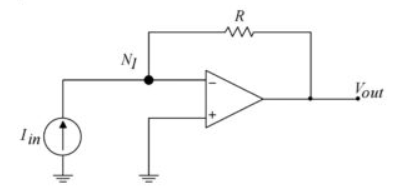
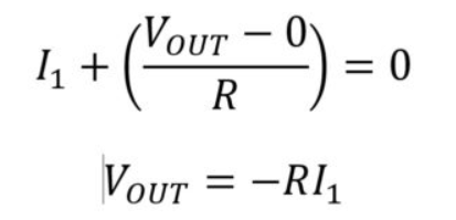
I am looking for a way to create a Transimpedance Amplifier like below (to convert current to voltage)


The problem now is how to add the current source?
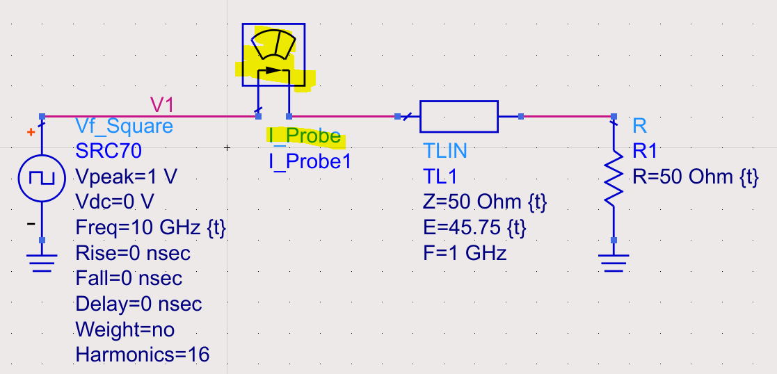
The current I want is the one read from I_probe like the circuit below.
How do I transfer this current to the Amplifier without affecting the circuit below?
(The frequency of Vf_Square can be very low, just I need to record the initial current when the voltage first goes up. According the the simulation, the initial current is kept until the voltage goes back down. That initial current is what I need for the amplifier)

1 Answer
That won't work beyond the GBW of the amplifier and certainly not with NFB at 10GHz. learn Transmission Line Theory and physical impedance characteristics of 3D metal structures like L/C ratios and LC products and how they are used to compute impedance and frequency. So your model is invalid. The basics come down to L/W or length of conductors or W/Gap in dielectrics. (1st principles in E/H field 2D geometry.)
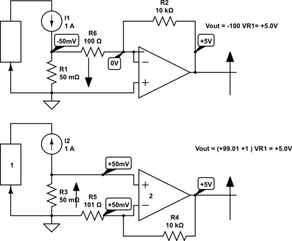
Your simple inverting amplifier does provide a negative resistance to the forward positive source impedance both sharing the same current with voltage gain by -Rfb/Rin. But it is currently limited to 20 mA or so, depending on OA. It's not really called a TIA because the impedances are both "resistive". But a current source to a voltage source or Cap to make a virtual low current inductor is possible. A Photovoltaic detector for example uses a TIA.
Current sensing with 50 mV / I max shunt.

simulate this circuit – Schematic created using CircuitLab
You may scale both R's up with any ratio you choose, but try to minimize input offset voltage from I*Rin differences.
-
\$\begingroup\$ What if I have the Vf_square frequency very low? Actually frequency does not matter to me, just I need to record the initial current when the voltage first goes up. According the the simulation, the initial current is kept until the voltage goes back down. That initial current is what I need for the amplifier. \$\endgroup\$– kintaroCommented May 25, 2022 at 23:54
-
\$\begingroup\$ An ammeter is basically a 100 mV galvometer with a milliohm shunt similar to a current source with a series shunt. Use an OA that can sense 50 mV below Vee with PNP type transistor inputs not Nch or NPN \$\endgroup\$– D.A.S.Commented May 26, 2022 at 0:01
-
\$\begingroup\$ Surge current sensors need a true Peak detector, Sample and hold comparator or similar \$\endgroup\$– D.A.S.Commented May 26, 2022 at 0:20
