5
\$\begingroup\$

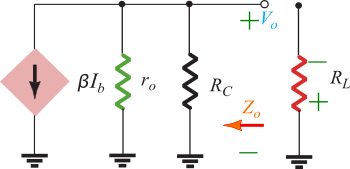
I read that a low output impedance is desirable for an amplifier. I am unable to understand why from my analysis of the output side of the common emitter amplifier. So looking at the output of the Common Emitter amplifier below, the output impedance is \$Z_{0}=r_{o}||R_{C}\cong R_{C}\$.

Output section of CE Amplifier

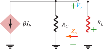
The load and \$R_{C}\$ will be in parallel with respect to the current source.

r0 removed

Let's consider the two extremes:

\$R_{C}=\infty\$ : \$R_{C}\$ branch is open so all the current will be flowing through the load. The load voltage is, \$\beta I_{b}R_{L}\$.

\$R_{C}=0\$ : \$R_{C}\$ branch provides a short for the current source so no current reaches the load. Load voltage is 0.

So what's going on? How come a low output impedance is desirable? Surely, something must be wrong with the way I'm analyzing the circuit!

\$\endgroup\$

4 Answers 4

8
\$\begingroup\$

In general

The output impedance of an amplifier is equivalent to a source impedance \$Z_{S}\$ from the perspective of a load with impedance \$Z_{L}\$. Think of a voltage divider where \$V_{\text{out}}\$ is the output voltage of the amplifier without a load (i.e. \$Z_{L} = \infty\$):
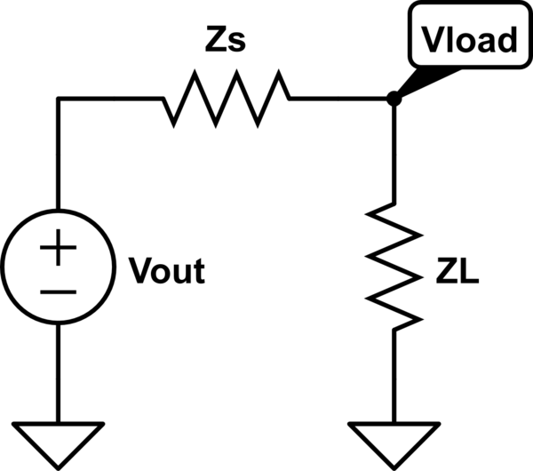
schematic

simulate this circuit – Schematic created using CircuitLab

The voltage delivered to the load is

$$V_{\text{load}} = \frac{Z_{L}}{Z_{L} + Z_{S}}V_{\text{out}}$$

If \$Z_{S} \gg Z_{L}\$ then \$V_{\text{load}} \approx 0\$, which is bad if you are trying to amplify a voltage for the load. But if \$Z_{S} \ll Z_{L}\$ then \$V_{\text{load}} \approx V_{\text{out}}\$.

For voltage amplification you want low output impedance from the previous stage and high input impedance from the next stage to maximize the voltage gain.

For current amplification you want the reverse: high output impedance from the previous stage and low input impedance from the next stage. Think of a current divider: the current will mostly flow through the lower impedance, so a low input impedance from the next stage means most of the current will flow into the load.

Your case

\$R_{C}\$ actually forms part of the load for the common emitter -- the total load to the common emitter is \$R_{C} \| R_{L}\$ where \$R_{L}\$ is the input impedance looking into the load. As in the general case you want to maximize the input impedance looking into the next stage, so you want to maximize \$R_{C}\$. In the limiting case where \$R_{S} = \infty\$ the only load is the input impedance looking into the load (i.e. \$R_{L}\$), which is the maximum load impedance you can get. In the limiting case where \$R_{C} = 0\$ the collector is shorted to \$V_{CC}\$ and there can be no voltage gain (the collector, which is the output node, is just shorted to the supply).
\$\endgroup\$
4
  • \$\begingroup\$ I understand the concept of voltage divider. My confusion is whats wrong with the way I analyzed the circuit. Explain the concept of voltage delivered using the current source in my first post. \$\endgroup\$
    – medwatt
    Commented Sep 23, 2014 at 6:03
  • \$\begingroup\$ The circuit that you're using is the Thevenin equivalent of my circuit, or my circuit is the Norton equivalent of your circuit. So in both, from the perspective of the load, Rth (Thevenin) and RN (Norton) are the same; i.e. They are both RC. But if you say RC=Infinity in the Norton Circuit, there's voltage across the RL. Now, in the Thevenin Circuit, if you say RC=Infinity, all the voltage is across RC and 0 across RL. I think this is why I am having problems. Why the discrepancy. Something is wrong somewhere ! \$\endgroup\$
    – medwatt
    Commented Sep 23, 2014 at 7:08
  • \$\begingroup\$ A current divider has a different topology than a voltage divider. How are you changing the topology of your example circuit? \$\endgroup\$
    – fouric
    Commented Nov 7, 2018 at 17:45
  • 1
    \$\begingroup\$ @fouric The output impedance of the current source would be in parallel with the input impedance of the load (i.e. a Norton equivalent current source with a load impedance. This is analogous to the Thevenin equivalent voltage source with the load impedance shown in my answer above, but for a current source. \$\endgroup\$
    – Null
    Commented Nov 7, 2018 at 18:56
7
\$\begingroup\$

For a current mode output, you want high impedance. For a voltage mode output, you want low impedance. For maximum power transfer, you want matched impedances. An ideal current source has infinite impedance while an ideal voltage source has zero impedance. Generally people work with voltage mode outputs, so that's why 'low impedance = good' is prevalent. In RF, everything is matched, generally to 50 ohms (both inputs and outputs). That output is current mode, so you want high impedance.

Also, Rc is not exactly the output impedace. If you transform that resistor and the source into a Thevenin equivalent, then it would be the output impedance and setting it to zero would be 'ideal'. This is not equivalent to setting Rc to zero in your circuit.

\$\endgroup\$
3
\$\begingroup\$

So what's going on? How come a low output impedance is desirable? Surely, something must be wrong with the way I'm analyzing the circuit!

Medwatt - the answer is simple: For a voltage amplifier (voltage output) a low output impedance is desirable - however, a simple circuit like the common emitter stage cannot fulfill your desire. If you want to follow the guideline for a low output resistor (example: Rc= 10 ohms in common emitter circuit) you will have practically no gain. That means: Good output resistance (low) of a circuit that cannot be used. Hence, a trade-off is necessary between two conflicting requirements (gain vs. output resistance).

Note, that such a trade-off is necessary in most of analog electronic circuits. As a consequence, a more complicated circuitry is needed to have high gain with a low output resistance - for example: A two-stage amplifier (common emitter in series with common collector).

(Many years ago, there was a song: "You always can`t get what you want".)

\$\endgroup\$
0
\$\begingroup\$

CONTEXT is important. Suppose you have an amplifier output terminal (RED and BLACK wire) connected to a SPEAKER (RED and BLACK wire). The music produced by the AMP is a waveform. And the objective is to produce that waveform on the speaker, one time, and not have any echo (of the waveform). A low-output-impedance amplifier assures there is a low resistance to GROUND (to attenuate any residual sound coming from the speaker when it reflects (the music waveform) into the amplifier).

\$\endgroup\$

Your Answer

By clicking “Post Your Answer”, you agree to our terms of service and acknowledge you have read our privacy policy.

Not the answer you're looking for? Browse other questions tagged or ask your own question.