1
\$\begingroup\$

This is a follow up to a previous question that I asked here

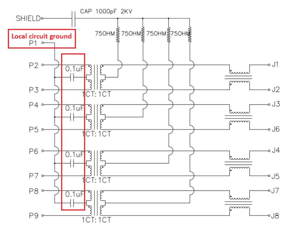
Why do we add capacitors on center taps to the magnetics when connecting to an Ethernet PHY?

enter image description here

Also what is the reason on why we terminate the other side of the magnetics with a resistor and a capacitor?

\$\endgroup\$

2 Answers 2

1
\$\begingroup\$

Why do we add capacitors on center taps to the magnetics when connecting to an Ethernet PHY?

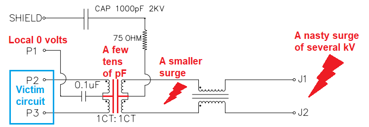
I would say that protection of victim electronics (blue below) from capacitively coupled line surges is going to have some part to play here: -
enter image description here

Despite the magnetics being an isolating transformer capable of substantially dealing with several kV surges, there is still capacitive coupling between PHY and line sides. The 100 nF capacitor is certainly capable of "containing" what is left from a line surge after passing through the CM filter and across the parasitic capacitance of the magnetics.

I did have a quick look on the internet but I was surprised to find that there wasn't clear-cut documentation about this. I'd like to be more confident about this but, it could certainly be there for diminishing the last remnant of surge current thus protecting the "victim circuits".

Also what is the reason on why we terminate the other side of the magnetics with a resistor and a capacitor?

Stack exchange Q and A on the Bob Smith termination.

\$\endgroup\$
7
  • \$\begingroup\$ Thank you for the answer. The link regarding the Bob Smith termination is the one I have referred. But the answer doesn't provide the reason on why it is used and what's the principle behind it. Could you help? \$\endgroup\$
    – user220456
    Commented Jun 7, 2022 at 16:07
  • \$\begingroup\$ I'm trying to figure it out right now. There does seem to be some element of "we always have used it" about this. \$\endgroup\$
    – Andy aka
    Commented Jun 7, 2022 at 16:08
  • \$\begingroup\$ Yes, I too checked that. Till now, going by the name of "Bob Smith Termination", I've assumed that it is placed to reduce reflections, since termination reduce signal reflections. But here, in the centre tap, there only seems to be power and no signals. So, I am a bit confused. \$\endgroup\$
    – user220456
    Commented Jun 7, 2022 at 16:12
  • 1
    \$\begingroup\$ I think that given the amount of disagreement on the internet we might never get to the bottom of it. I remember looking before (some years ago) and was equally dumfounded by the opposing viewpoints. \$\endgroup\$
    – Andy aka
    Commented Jun 7, 2022 at 16:14
  • 1
    \$\begingroup\$ @Newbie well unless someone publishes some form of technical report on this that covers all the bases, we might never really know. I can see that there is some benefit against surges; after all, why is the capacitor rated at 1 kV if it didn't handle indirect-lightning surges al la EN6100-4-5 so, I can see that the centre-tap is a clean place to put the 75 ohm resistor in order to CM dissipate surges but, nobody seems to be talking about this so, I'm guessing. \$\endgroup\$
    – Andy aka
    Commented Jun 7, 2022 at 16:21
1
\$\begingroup\$

Why do we add capacitors on center taps to the magnetics when connecting to an Ethernet PHY?

Normally we don't have to. I mean, it depends on the PHY chip. Most applications suggest that the PHY-side centre tap of the eth magnetics should go to the positive supply (e.g. 3.3V). So, that capacitor basically serves as a decoupling capacitor for those applications, but it's not always necessary.

Also what is the reason on why we terminate the other side of the magnetics with a resistor and a capacitor?

That cable-side termination is called "Bob Smith termination". I'll not dive into details about it as there are numerous explanations out there already. Study it and if you find some details that you don't understand then ask.

\$\endgroup\$

Your Answer

By clicking “Post Your Answer”, you agree to our terms of service and acknowledge you have read our privacy policy.