0
\$\begingroup\$

schematic

simulate this circuit – Schematic created using CircuitLab

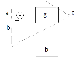
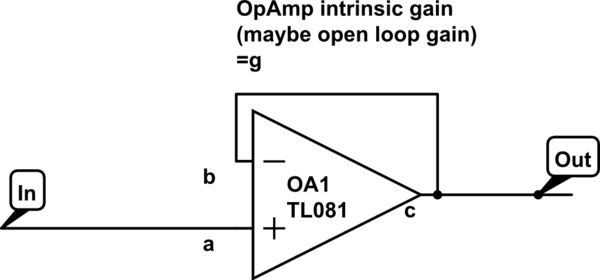
In this circuit, the input is continually summing with its negative through negative feedback, so it must become zero on the output. Why is the output not zero then?

As all of us know: c=(a-b)g

In our case:

c=(a-c)g -> c= ag-cg -> c(1+g)=ag -> c=ag/(1+g)

As we know g is very high and c must become a. (The calculation has some deficit and has been corrected according to answers, but mere math's behind is not my question).

Despite the calculation, this behaviour is not intuitive and I'm eager to find an intuitive explanation.

\$\endgroup\$
6
  • 4
    \$\begingroup\$ "then it must become zero on the output" No, it must become zero between the input and the output. When + input higher than - input, the opamp increases the output. WHen + input is lower than the output, the opamp decreases the output. \$\endgroup\$
    – DKNguyen
    Commented Jun 12, 2022 at 7:40
  • \$\begingroup\$ @DKNguyen If OpAmp just try to zero difference between + and -. Then in the circuit above flip the OpAmp around horizon. Again output must follow the input, but it won't! \$\endgroup\$ Commented Jun 12, 2022 at 7:53
  • 2
    \$\begingroup\$ No, you are confusing what the opamp does with what the circuit does. The op amp alone without the feedback loop just amplifies the voltage difference between the inputs by nearly infinite gain. What I said in my first comment is what the circuit (the opamp with the negative feedback loop) does, not what the opamp alone does. \$\endgroup\$
    – DKNguyen
    Commented Jun 12, 2022 at 8:34
  • \$\begingroup\$ @DKNguyen Why and how circuit do that? have see my calculation on question? \$\endgroup\$ Commented Jun 12, 2022 at 8:45
  • \$\begingroup\$ "input is continually summing with its negative" is not true. Please refer to the simple rules how op-amps work. \$\endgroup\$
    – Justme
    Commented Jun 12, 2022 at 10:57

6 Answers 6

23
\$\begingroup\$

There is a g missing in the equations:

\$c = (a-b)g\$

\$c = (a-c)g\$

\$c = ag - cg\$

\$c + cg = ag\$

\$\frac{c}{g} + c = a\$

As g tends to infinity, a tends to c.

\$\endgroup\$
11
\$\begingroup\$

in our case: c=(a-c)g -> c= ag-cg -> c(1+g)=a -> c=a/(1+g)

You have made a mistake in your math but your first statement is correct: -

$$c = g(a-c)$$

And here's where you went wrong because this expands to: -

$$c= \dfrac{ga}{1+g}$$

So, if g is very high, \$c = a\$.

\$\endgroup\$
8
\$\begingroup\$

There is no absolute zero: the amplifier doesn't know what zero is.

The amplifier does only one thing: amplifies the difference between the (+) and (-) inputs by a large gain, and puts it on the output. You then provide feedback that utilizes the large gain to do what you want.

With direct output-to-(-) feedback as you show, the action of the amplifier becomes to bring the difference between the inputs very close to 0V. The absolute voltage on the (+) pin is called the common mode voltage, and it can be arbitrary, within the limits provided in the datasheet specifications. In a voltage follower, the common mode voltage is replicated on the output.

More specifically: in a voltage follower, the difference between the (+) and (-) inputs is zero when the output, shorted to the (-) pin, is at the same voltage as the (+) pin. Thus, since the action of the op-amp is to null the difference between (+) and (-) when stable negative feedback is present, the (-) input will follow the (+) input, and the output is simply shorted to the (-) input, so it has to follow the (+) input.

\$\endgroup\$
3
  • \$\begingroup\$ I've updated question if you could plz revisit, A-A must become zero, don't matter what is A or not need to understand it! I still need time to digest your answer, thanks so much. \$\endgroup\$ Commented Jun 12, 2022 at 8:25
  • \$\begingroup\$ You've inspired me to use that calculation, thanks. \$\endgroup\$ Commented Jun 12, 2022 at 14:43
  • \$\begingroup\$ "the amplifier doesn't know what zero is." contradicts the fact the amplifier has to output something when a=b \$\endgroup\$ Commented Jun 13, 2022 at 8:51
3
\$\begingroup\$

If one were to assume a practical op amp would only be used in circumstances where external feedback effects were instantaneous, its behavior could be described as:

  1. If the non-inverting input is non-trivially higher than the inverting one, make the output rise as quickly as possible.

  2. If the inverting input is non-trivially higher than the non-inverting one, make the output fall as quickly as possible.

  3. If the inputs change in such a manner as to become equal, leave the output where it is.

While op amp behavior is often described as being a linear function of gain, many op amps are in fact decidedly non-linear in their behavior and in fact behave in a manner more like the above. In cases where the inputs are only minimally different, the output may swing slowly, but unless the inputs are close to each other the output swing rate will be essentially independent of the difference between the inputs.

What's important to note with an op amp is that if the feedback is instantaneous, the output will stabilize at the positive rail, bottom rail, or a point which causes the inputs to be at most trivially different. The only behavioral aspects that will be affected by op amp characteristics will be (1) what level of difference is "trivial", and (2) how quickly the op amp's output can swing. Provided that #1 is small enough and #2 is fast enough to satisfy an application's requirements, there will be no need to do any further analysis of the op amp's behavior.

Many people who use op amps for audio circuits assume a linear model, even when using an op amp like the 741 whose behavior is more like the above. This has led to the saying that the 741 is uniquely suitable for taking an absolutely beautiful pristine audio signal and ruining it. On the other hand, the simple three-way analysis above makes it easier to predict the behavior of some op amps than would the linear model.

\$\endgroup\$
9
  • \$\begingroup\$ There is a lot of philosophy in your answer.... Here is my universal method for understanding op-amp circuits with negative feedback: In the first moments, when the input voltage changes, think of op-amp not as a proportional device (amplifier) ​​but as an integrator. Then, this "integrator" gradually becomes an amplifier and reaches the point of equilibrium. You can even think of an op-amp as a "dynamic amplifier" that smoothly changes its gain from zero (at the beginning of the change) to a maximum (at the end of the change) when it reaches equilibrium... \$\endgroup\$ Commented Jun 12, 2022 at 19:34
  • 1
    \$\begingroup\$ @Circuitfantasist: The "as fast as possible" was deliberately vague, because while op amps often act somewhat like integrators, they're not generally specified to do so. The op amp might not be capable of swinging its output as fast with very small (borderline-trivial) differential inputs as with larger ones, but there's often no guarantee that it will swing them slowly. \$\endgroup\$
    – supercat
    Commented Jun 13, 2022 at 14:53
  • \$\begingroup\$ Could you please tell me more about the difference between your model and the linear model (c=(a-b)g, which is equal to the three phrase mentioned in your answer when g=inf)? \$\endgroup\$ Commented Jun 15, 2022 at 14:04
  • \$\begingroup\$ @mohammadsdtmnd: A mathematically ideal op amp would be extremely prone to oscillation as a result of, if nothing else, the time required for an electrical signal to pass through the feedback path. Many practical op amps have some kind of circuitry that limits the input response to prevent oscillation in common usage scenarios. Provided the amps are responsive enough to meet requirements, but not so responsive as to become unstable, an application designer need not be concerned with quantifying the op amp's exact degree of responsiveness. \$\endgroup\$
    – supercat
    Commented Jun 15, 2022 at 15:23
  • \$\begingroup\$ @mohammadsdtmnd: Further, the ideal model would suggest that in a typical inverting amp scenario where the non-inverting input stays at DC, the inverting input would have a recognizable signal at a tiny fraction of the output amplitude, but on most practical amps the only thing that can really predicted about the voltage on the inverting input is that unless the op amp is being pushed to its limits that signal will be small. \$\endgroup\$
    – supercat
    Commented Jun 15, 2022 at 15:29
2
\$\begingroup\$

What is the basic idea?

First of all, you need to find out what the hell this is all about... what the basic idea is here... and not just in this electrical implementation. Because it is a great idea that we can see all around us and we ourselves constantly realize it in various life situations. That is why I prefer to call it by such figurative names as "principle of life" and "active copying" rather than by the generally accepted "negative feedback".

The basic idea

The problem solved by this idea is simple - to make a quantity Y (Vout here) equal to another quantity X (Vin)... but it is realized in a complex way:

First Y is produced by another (different from the input) source (Vcc), then it is compared by subtraction with X and finally changed to the correct direction until Y = X (Vout = Vin) is reached.

Voltage follower

In the circuit of an op-amp follower, Vout is produced by a properly supplied op-amp, and the two voltages Vout and Vin are subtracted by contrary connecting them in series. The result of this subtraction is a "floating" voltage Vout -Vin that requires an op-amp with a differential input (take a look at this Wikibooks story in which my students "invented", step by step, the op-amp follower and then turned it into an amplifier).

It is interesting that this idea was invented and implemented in electrical form a long time ago - in the 19th century. This made it possible to make an "ideal" voltmeter without any electronic gadgets such as transistors and operational amplifiers. In my story "Ideal" voltmeter (for now, only in Bulgarian), I have told in detail how together with my students I reproduced this famous experiment in the laboratory in order to show the power of this idea. Here are three pictures from the story:
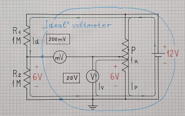
19th century electrical follower ('ideal voltmeter')

19th century electrical follower ("ideal" voltmeter)
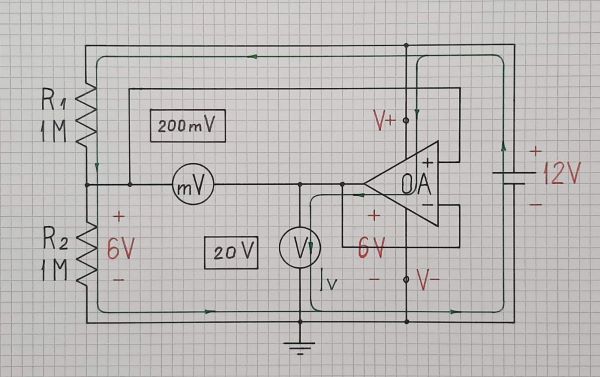
21st century op-amp follower
21st century op-amp follower

21st century op-amp follower - conventional

21st century op-amp follower - conventional circuit diagram

Voltage inverter

In contrast, in the circuit of an op-amp inverter, the two voltages are subtracted by a 2-resistor summing circuit. Its output voltage is referenced to ground; so the op-amp input can be single-ended.

Benefits

The benefit of all this is that the load (next stage) will consume current from Vcc and not from Vin. Vout is a "powerful copy" of Vin, hence the name "buffer" or "booster".

EDIT: What does the op-amp actually do?

(a response to @mohammadsdtmnd's comment)

But when c=a then c=g(b-at) became 0*inf and must be clarified. How OpAm handles (regulates) this subtraction to outcome a replicate?

This topic is often discussed in this forum and good classic explanations are given. But now I will present a new intuitive explanation of the transition process, which came to me a while ago in response to your comment (thanks!).

My insight

Let's define two types of op-amp gain, which we can figuratively call dynamic and static (or, if you prefer, measured and actual).

The dynamic gain is determined by the ratio of the output voltage to the input differential voltage (between the two op-amp inputs) at some point in time. Due to the op-amp inertia (although very small) it changes in time from zero (at the beginning of the transition) to the value of the static gain (at the end of the transition).

The static gain determines the ratio of the output voltage to the input differential voltage (between the two op-amp inputs) at the end of transition. This is the gain given in the op-amp datasheet.

Now we can explain the op-amp behavior. We can imagine it as a control system that (like everything in this world) seeks to reach the equilibrium point. What is it?

The op-amp reaches its state of equilibrium when the dynamic gain equals the static gain.

In other words, when the input voltage changes, the op-amp begins changing its output voltage (and indirectly, its differential input voltage) so that to make the ratio between them equal to the op-amp gain.
\$\endgroup\$
6
  • \$\begingroup\$ Wait a minute ... ! What meaning it is to <<compared by subtraction>>? you mean subtraction, addition, multiplication and or maybe taking fft, means comparing? \$\endgroup\$ Commented Jun 12, 2022 at 14:41
  • \$\begingroup\$ @mohammadsdtmnd, Look at this Wikibooks story about the comparison by series subtraction... \$\endgroup\$ Commented Jun 12, 2022 at 14:47
  • \$\begingroup\$ ... and another story about the parallel summer. \$\endgroup\$ Commented Jun 12, 2022 at 14:50
  • \$\begingroup\$ Inspiring, thanks I will read them all . \$\endgroup\$ Commented Jun 12, 2022 at 14:58
  • 1
    \$\begingroup\$ I've read all, thanks. But when c=a then c=g(b-at) became 0*inf and must be clarified. How OpAm handles (regulates) this subtraction to outcome a replicate? Partially I,be understood, how sum or subtract by series voltage, but not got, how it regulate subtraction to output a replicate? \$\endgroup\$ Commented Jun 14, 2022 at 10:52
-4
\$\begingroup\$

Other than that calculation mistake(mentioned by devnull and Andy aka), you need to consider the model more accurately to understand the question: Does it really subtract input from output or not. The OpAmp model (by unity feedback b=1 and g=inf):

OpAmp feedback model

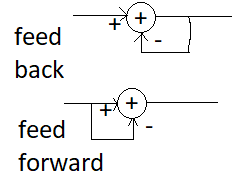
Assume we have input at a. As you can see, this feedback model can't really achieve this direct cancellation of input with input-input=0 (In question I've asked why output doesn't become 0). To dive more into the paradox. Load in your mind two system, feedback and feedforward:

feed model

Assume input is in left path and out is in right path of above picture. In feedforward it's straightforward: out=in-in=0 (zero at all time) But in feedback case, output is: out=in-out=...=in/2. Assume initially we have zero everywhere in above picture we don't have opamp so we don't have infinite gain. Now: Input signal becomes 1, input can't be zero anymore, the output must become something which it's difference from input being equal to output, to not cause difference change. Yes, it must be 1/2 which is compatible with out=in-out=...=in/2.

In feedback scenario (in first picture with opamp model), you can only reach zero output if make feedback gain b=inf and feedforward gain b=inf. ( in this manner the special zero will be created on c instead of before g block)

Now, does really unity gain opamp subtract input from output or not. Ans: Because g is inf a must be really close to b, otherwise output will saturate to rails. this is why we always assume voltage of a is equal to b. The for the sake of b=1 c also must be equal to a. Ans the more the g is, the more c will be close to a. Since larger g means a need to be more close to b.

The OpAmp model is feedbacked one, and you can only reach output being 0 all the time by using another OpAmpinstead of b block in OpenLoop state.

https://electronics.stackexchange.com/questions/623974/opamp-with-negative-feedback-model-oscillates

\$\endgroup\$
8
  • \$\begingroup\$ 3 dwnvote + no comment, Why? tel me whats wrong. As a questioner I know what I want, I've just shared what I've got in couyntering that problem. \$\endgroup\$ Commented Jun 17, 2022 at 16:55
  • 6
    \$\begingroup\$ I downvoted for two reasons: (a) your answer is not clear and (b) accepting your own answer comes across as rude / selfish. People have made efforts to help you and you only reward yourself. \$\endgroup\$ Commented Jun 18, 2022 at 8:39
  • \$\begingroup\$ @DamienD This is not about selfishness, the reward is nothing for me, there is no reputation reward to me. And the persons who answered has got their upvote and they reward they deserve. but those are not the answer really I wanted to know. But they really inspired me to understand what I want to know, this means they have not completely quenched my thurst of curiosity. And I've shared my knowledge. It on you to think what's in my mind. But you can choose optimism. And ok I will improve it on my free time. \$\endgroup\$ Commented Jun 18, 2022 at 18:50
  • 1
    \$\begingroup\$ @mohammadsdtmnd, I have upvoted your answer because you have shown original thinking... and since it is very rare, it should be encouraged. Anonymous downvotes do not deserve to be commented on. About your explanation: It is interesting to do a thought experiment with an amplifier with variable (programmable) gain from one to infinity and to observe how signals depend on the gain. In 90's, I even wanted to make such a real experiment (see a yellowed circuit diagram of such an inverting amplifier that I sketched on June 6, 1990 in Bulgarian). \$\endgroup\$ Commented Jun 27, 2022 at 21:14
  • 1
    \$\begingroup\$ @Circuitfantasist Though thanks for totally unreadable photo text. :) \$\endgroup\$ Commented Jul 5, 2022 at 4:23

Your Answer

By clicking “Post Your Answer”, you agree to our terms of service and acknowledge you have read our privacy policy.

Not the answer you're looking for? Browse other questions tagged or ask your own question.