0
\$\begingroup\$

I'm trying to add a reset button to my circuit which will temporarily cut the power to the circuit when a button is pressed.

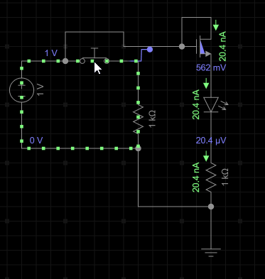
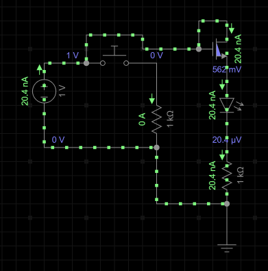
I thought about using a transistor, and short-circuiting the gate to ground via a resistor. This works in EveryCircuit, but not on the breadboard.

My circuit uses an N-channel MOSFET.

The circuit below should be 5 V, and the same problem occurs with 5 V.

Push button up Push button down

Is EveryCircuit not modelling reality correctly, do I have the wrong solution, or perhaps it's the correct solution but I've wired up the breadboard incorrectly? What could be a better solution to this problem (other than using a physical toggle switch)?

\$\endgroup\$
2
  • 3
    \$\begingroup\$ Why not use a push-to-break switch? \$\endgroup\$
    – HandyHowie
    Commented Jun 24, 2022 at 13:29
  • \$\begingroup\$ Solution is to use P-channel. Many thanks to Andy aka. \$\endgroup\$ Commented Jun 24, 2022 at 15:45

2 Answers 2

4
\$\begingroup\$

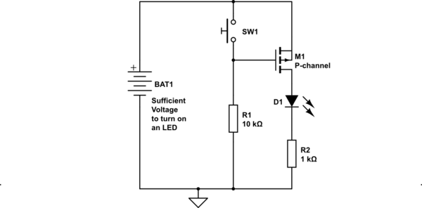
This is probably more like what you need: -

schematic

simulate this circuit – Schematic created using CircuitLab

Regarding your circuit posted: -

  • 1 volt won't turn an LED on and it'll be barely enough to turn the MOSFET on.
  • The pushbutton in your circuit will have zero effect on functionality.
  • Using the FET as a source follower is not going to work very well either.
\$\endgroup\$
5
  • \$\begingroup\$ Oops, that was meant to be 5V. Actually my bench power supply was 5V for the breadboard. I didn't re-create it accurately in that case. \$\endgroup\$ Commented Jun 24, 2022 at 15:23
  • \$\begingroup\$ I submitted an edit to clarify that your answer is for a P-channel MOSFET; I was using an N-channel instead of a P-channel. Oops! \$\endgroup\$ Commented Jun 24, 2022 at 15:31
  • 1
    \$\begingroup\$ It does say P channel in the diagram and it is the circuit diagram that always takes precedence over text. \$\endgroup\$
    – Andy aka
    Commented Jun 24, 2022 at 15:36
  • \$\begingroup\$ I understand, and from the perspective of an expert, you're technically correct. On the other hand, I'm thinking about it from the perspective of a novice; when you're learning electronics for the first time, spotting component differences between schematics is harder than you might remember. So, it wasn't initially obvious that your solution was effectively the same as mine but with a P-channel instead of an N-channel. I believe that it might help other novices if you took extra care to highlight that all I needed was a P-channel instead of an N-channel. \$\endgroup\$ Commented Jun 24, 2022 at 15:44
  • 2
    \$\begingroup\$ Sorry, I read that back and it sounds churlish. That wasn't my intent. I really appreciate your help. Thanks. \$\endgroup\$ Commented Jun 24, 2022 at 15:54
1
\$\begingroup\$

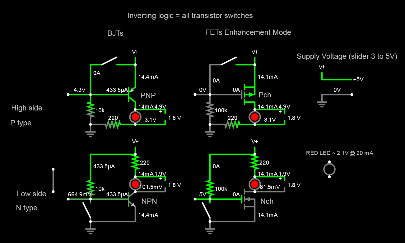
Pay close attention to input to output differential level voltages. All common emitter or common source are inverting switches.

Bipolar Junction Transistors (BJT) use base-emitter current , while FETs use Gate-Source charge voltage as controlled inverting logic switches.

Here are 4 ways with 2 types and 2 sides to solve using a momentary switch to cut (low) power. enter image description here

The load current depends on the Diode rated voltage and current thru or voltage across the current limiting series R. (I=V/R) Here I chose a medium-low current and variable voltage such as from 3V battery to 5V supply. The transistor types for FETs have variable threshold voltage and ON resistance or 1/gm. For BJT's the Ron depends on the power rating and current.

\$\endgroup\$

Your Answer

By clicking “Post Your Answer”, you agree to our terms of service and acknowledge you have read our privacy policy.

Not the answer you're looking for? Browse other questions tagged or ask your own question.