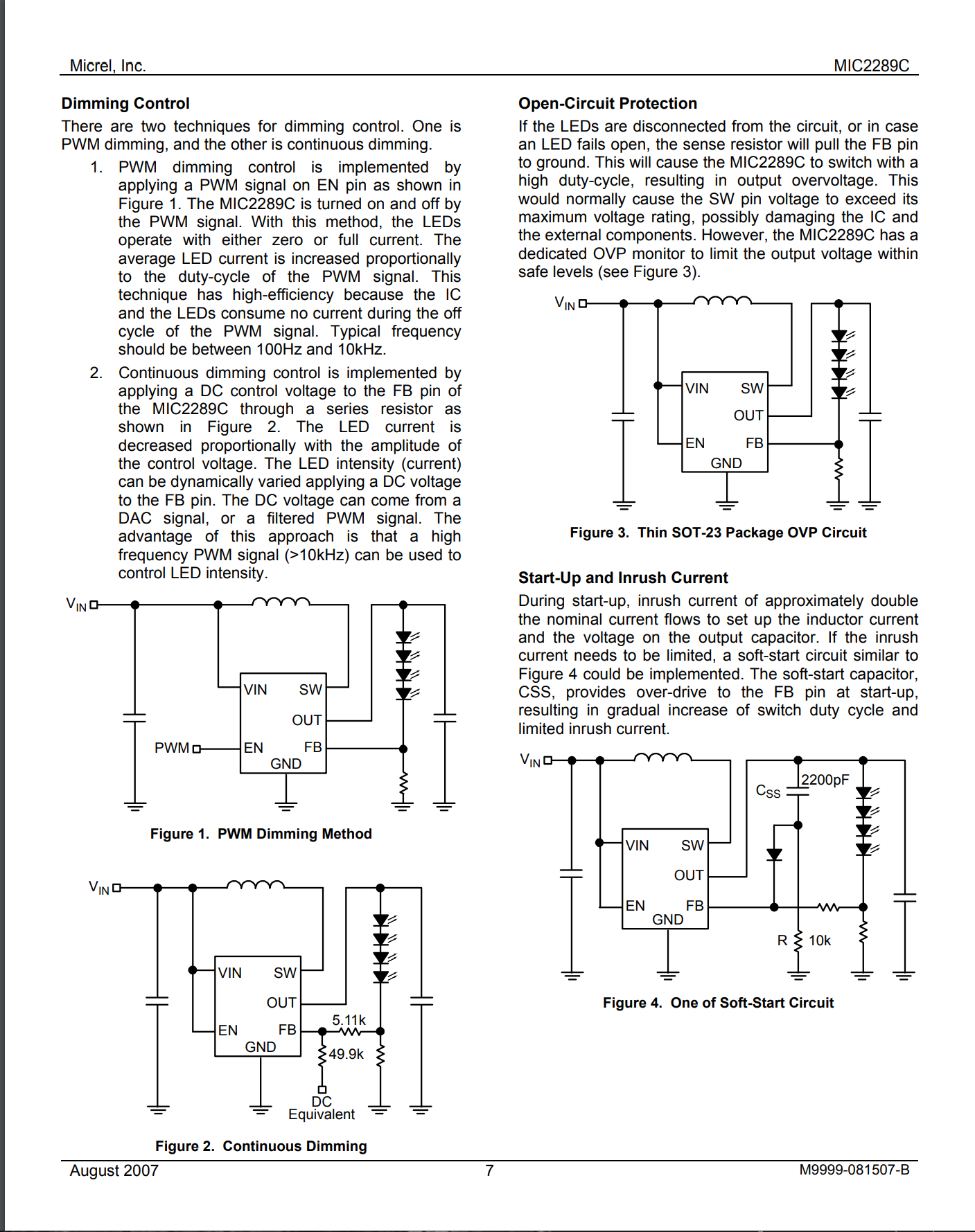
I am looking to use the MIC2289C LED backlight driver from Microchip in a circuit and have a question about the unnamed resistor that connects to the FB pin of the driver and the cathode of the LED string. Does anyone have intuition why it is there and what a recommended value for it would be? I am looking to control dimming via PWM as you see in Figure 1 and incorporate the recommended inrush current in Figure 4. My understanding from reading the datasheet is that the resistor from LED cathode to ground should be held at 95 mV and your resistor is chosen based on LED display current draw (40 mA). Since the other diagrams show a direct connection to the FB pin, I am not sure what the additional resistor does. My guess is that it they left it in to show how to incorporate it when using the continuous dimming circuitry and that it is not needed when using PWM dimming.
3 Answers
It is only necessary if you want to modify the LED current in a continuous way. The resistor allows you to modify the V seen at the FB pin to be a combination (sum) of the actual sense R voltage and the additional applied signal.
In simple PWM it is not necessary.
Does anyone have intuition why it is there and what a recommended value for it would be?
Yes, given that the FB input node (when regulating) will be at 95 mV, the current through the LEDs AND the "unknown" resistor will produce 95 mV. So, if you want 100 mA through the LEDs, the "unknown" resistor value is simply ohm's law i.e. R = V/I = 0.95 Ω.
There is no recommended value; you choose the resistor value to suit the current you need flowing in the LEDs.
I am not sure what the additional resistor does. My guess is that it they left it in to show how to incorporate it when using the continuous dimming circuitry and that it is not needed when using PWM dimming.
The circuit that uses the two resistors interposed between FB and the "unknown" resistor allow you to "con" the controller chip into thinking it has reached 95 mV across the "unknown" resistor thus, by varying the voltage called "DC EQUIVALENT" you can dim up or down over a range of values.
So yes, your assumption is correct.
-
\$\begingroup\$ Thank you for the detailed answer. Yours and the others above were very helpful. I had put a footprint for a resistor just in case, sounds like I just need a 0 ohm jumper for PWM control mode then. \$\endgroup\$– jakobCommented Jul 26, 2022 at 22:58
What I see in Fig 4 is the soft start RC feedback controlled by 10k only when the diode is conducting much more than the "unnamed" series R from the shunt. Thus when choosing that include the parallel effects on T=RC for soft start, but don't make it too high for stray noise immunity and certainly much less than the input loading effects from FB current.
A convenient value is make both 10k.

