The method you propose could be an option but it is complicated to implement in an integrated circuit. You would need to sense the input current and voltage then do a multiplication and compare it with a maximum value. This is technically complicated - multiplier are not simple cells - and costly silicon- and components-wise. One way to overcome this is to observe the feedback voltage which is representative of the peak current hence the transmitted power. Actually, what is wanted is not exactly the absolute power value that the converter delivers, but more a limit of the maximum power the load can see in low- and high-line conditions, when the current sense setpoint hits the maximum limit.
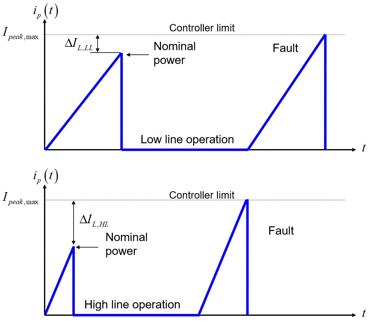
It is a known fact that switching converters deliver more power at high line than at low line: peak current overshoot due to propagation delays, transition from CCM to DCM, higher switching frequency in QR etc. This is covered in a 4-part series of articles I published in How2Power entitled The Over-Power Phenomenon In DCM/CCM-Operated Flyback Converters. This phenomenon is exacerbated in a QR converter as shown in the below figure:

You see that in low-line conditions, you will design to have some margin so that the converter delivers its nominal power while the peak current is still below the limit. The switching frequency is the lowest. Should you increase the power slightly, the peak will soon touch the limit and protection will trip. Now, power the converter from a high-line input and the frequency increases for the same nominal power than at low line. As a result, the operating peak current is naturally much smaller. As the picture shows, the peak is now far away from the limit and you could deliver much more power before tripping the protection. This is an issue for the semiconductors and various components but for the downstream load as well in case of failure. What you need is a way to reduce this peak excursion between low- and high-line operations. This is called over-power protection or OPP.
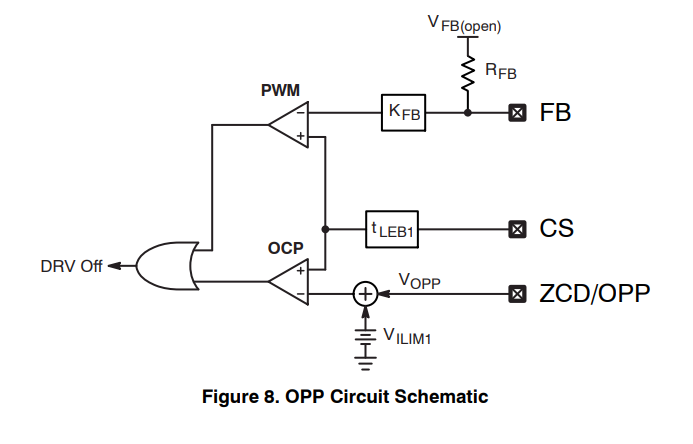
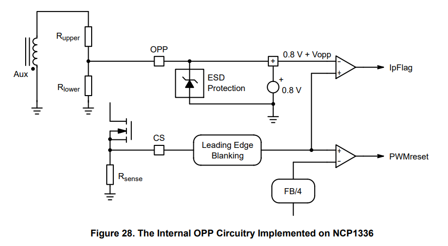
You can do this through different methods - some are proprietary - like offsetting the current-sense voltage in relationship with the rectified bulk or, as proposed in the circuits you mentioned, use the negative voltage present on the auxiliary winding during the on-time:

This negative voltage depends on the transformer turns ratio for the auxiliary winding and the rectified bulk voltage. It will be low at low line and much higher at the maximum input (a ratio of 3 from 120 to 370 V). If you add this negative voltage to the positive peak current setpoint of 0.8 V for instance, then you see that you almost have the maximum peak current at low line but much lower in high-line conditions. As the pictures shows, it nicely keeps the maximum power under control which is mandatory for passing the limited power source tests or LPS.


