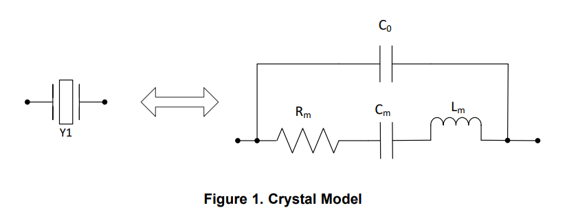
A test jig is simple enough: as the resistance of interest is near 50Ω, we can just use the function generator's output impedance (assuming it's well behaved, of course). A typical setup might be: cable from function generator to oscilloscope; BNC tee on scope; crystal attached to tee via suitable adapter (BNC to binding posts?). The cable length from tee/scope to crystal should be short, but isn't a huge limitation at this frequency (hence why binding posts and fly leads are acceptable).
Note that the function generator must be very stable. A clean digital, synthesized (PLL locked), or at least low-drift LC type, is probably necessary. (I know for a fact, I tried similar measurements with my Wavetek 193 (an RC timer based unit) and got very poor results!)
To calculate the resistance, find the series resonance (minimum amplitude), and read the voltage. Disconnect the crystal and measure again. Take the ratio, do a little math, and solve for R.
Co acts as an impedance converter. We can assume ESR is the dominant loss in the circuit, but the measured value may differ due to this transformation effect.
Note two things:
- At resonance, X = 0.*
- Co's reactance is canceled out by the crystal being on the slightly inductive side of its actual resonant frequency (so, it will be detuned by, say, a few 100 Hz?).
*One more wrinkle: there are different kinds of "resonance". Do we take min(|Z|)? Do we take X = 0 instead? (Measure phase by taking a reference waveform from the function generator's sync output; measure the baseline phase shift with no crystal connected, and subtract that from the live reading.) In general, these need not be the same points -- they happen to be so for the simplest (only series/parallel) resonant networks, but not in general!
If we know (or feel confident guessing) Co, we can solve for L and R based on measured R (at X = 0). This is a simple enough calculation, so we should pick this definition, and accordingly use the appropriate measurement method(!).
Solving for L and C is easy enough: for X = 0, ω = ω0, and so XC = XL. Solving for R in terms of terminal resistance gives us,
$$ \mathbb{Re}\{Z(X=0)\} = R \left[ 1 - \left(1 \pm \frac{R}{Z_0}\right)^2 + \left(1 \pm \frac{R}{Z_0}\right)^4 \right] $$
which, isn't exactly a straightforward form in terms of \$R\$, but perhaps we can let a computer solve it numerically, and let that be good enough.
In the above equation, the left-hand quantity is the resistance measured, at the frequency which gives zero reactance (zero phase shift relative to pure resistive load, or unloaded). \$R\$ is the ESR, and \$\omega_0\$ and \$Z_0\$ are the resonant frequency and impedance of the effective LC matching network thus formed (i.e., C0 and the leftover part of Lm, in the diagram). The \$\pm\$ are for the respective solutions (\$\omega = \omega_0 \left( 1 \pm \frac{R}{Z_0}\right) \$, one of which we can likely ignore due to the below statement, but I'd have to do more work to tell which one).
Mind, I solved this on the assumption that the motional reactance is purely inductive (that is, completely leaving out Cm) -- probably a poor assumption, but how poor, I don't know offhand.
C0 can be measured at most any frequency off-resonance; it's the dominant impedance at most frequencies, except in narrow bands where motional coupling occurs. You need a precise meter to read such small values of course, and be careful about case capacitance (ground it, if applicable) and lead lengths.
Probably, just doing the complex math directly (rather than all the algebra!), or say plotting it on a Smith chart, is easier than solving it symbolically like this. Since these are small corrections (\$Z_0 \gg R\$) there's probably a bunch of other things that can be done here (e.g. replace \$Z_0\$ with \$C_0\$ and substitute \$\omega_0\$ through a few times??). I'll let others fill in if they like.
Alternately, C0 can simply be canceled out: once it's measured (with a low-frequency / broadband / general technique), connect \$L = \frac{1}{(2 \pi F)^2 C}\$ in parallel, and measure ESR straightforwardly.
 (from https://www.ti.com/lit/an/snla290/snla290.pdf)