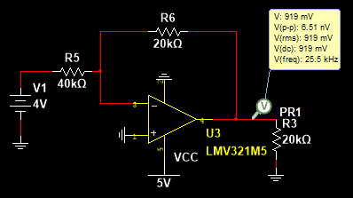
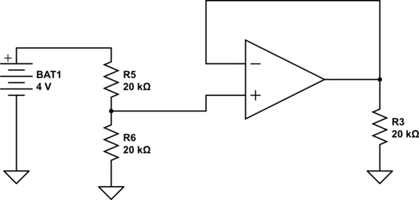
You have wired your setup as an inverting opamp, but you have used the formula for a non-inverting opamp. If you plug the in the resistances, you get the expected 0.5 gain, but with an inverted output. If you followed this by a second inverting unity opamp, you would get the final result of an attenuated signal.
However, if you want to use a single non-inverting opamp, lets take the formula: Gain = 1 + Rf/Rin. See the 1. Thats a problem. This means that to get an attenuation one of Rf or Rin must have negative resistance, which means an active circuit, not something possible with a simple resistor.
Thats the maths, for a more intuitive understanding, opamps are amplifiers, the opamp is amplifying the input difference, which is retarded by the negative feedback to a controlled gain. In order to achieve an attenuation, that feedback needs to be inverted, applying feedback to increase the apparent strength of the input signal. The problem with that is you end up with an unstable oscillator topology as any noise is amplified in a loop instead.
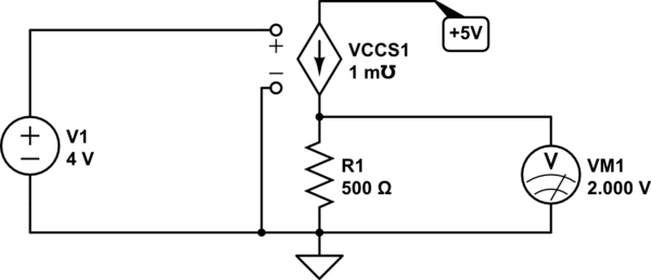
Part of the problem in understanding your question is that a fixed attenuation circuit with one input and one output isn't going to solve your problem of (V1/V3-V2) if you view V2 and V3 as voltages and not resistors. You need a voltage controlled attenuator, and those are not trivial. However, you mention that their are only 4 values of (V3-V2). As such I would suggest you achieve your problem by selecting the value of (V3-V2) in the digital domain by having the switches wired as logic lines into a subtraction IC, and use that with a decoder to select the resistor to switch into the divider using a MOSFET.


