4
\$\begingroup\$

Assume we have a purely inductive circuit such as below:

voltage source and inductor

To calculate the most general case, \$V_1\$ is given as such:

$$v(t) = V_m \cdot \cos(\omega t+\theta)$$

For an inductor, \$v(t) = L \dfrac{\mathrm{d}i(t)}{\mathrm{d}t}\$. Writing it in integral form:

$$i(0)+\int_0^t{v(t)\mathrm{d}t}= i(t)$$

Now consider \$i(0)=0\$, meaning there was no current in the system before the source was on:

$$\int_0^t{V_m\cdot \cos(\omega t+\theta) \mathrm{d}t}= i(t)$$

Moreover, the result of the integral, and hence the current:

$$\dfrac{V_m}{\omega}\cdot(\sin(\omega t+\theta)-\sin(\theta))= i(t)$$

If transformed to their complex counterparts via \$\mathrm{e}^{j\omega t} = \cos(\omega t)+j\sin(\omega t)\$, the result, which is the impedance, is not \$j\omega L\$ but some term similar to \$j\omega L\$, but also containing the phase of the voltage source, which shouldn't be there, since impedance is not dependent on the phase of the source.

Where am I going wrong?

\$\endgroup\$
8
  • \$\begingroup\$ Impedance is only defined in the steady state. Your expression seems to include the startup transient as well, with an arbitrary phase depending on where you take your t=0. \$\endgroup\$
    – Neil_UK
    Commented Sep 18, 2022 at 12:50
  • \$\begingroup\$ I assume initial conditions as zero, isn't that what makes it steady state? , if not, where should the adjustment be \$\endgroup\$
    – ozgun can
    Commented Sep 18, 2022 at 13:00
  • \$\begingroup\$ Zero! Zero current, or zero voltage? Work out both, and post the results. They are different, and have different transients. Remember impedance is what you get when the initial transient has died down. In a circuit with no resistors, there's no loss, and the initial transient never dies down, so it's going to be quite difficult to intuit what it is. As you have a simulation, put in a small amount of series R, and simulate it until the transient has finished. \$\endgroup\$
    – Neil_UK
    Commented Sep 18, 2022 at 13:05
  • \$\begingroup\$ Impedance is a property of a passive element that is independent of any signal. It exists whether or not the current and voltage are present. It is the transfer function for transforming current into voltage. The initial condition has nothing to do with impedance. \$\endgroup\$
    – user319836
    Commented Sep 18, 2022 at 13:10
  • \$\begingroup\$ if so, is there anyway that you calculate the impedance from voltage in the definite integral form of inductor current, which is from time= minus infinity to present \$\endgroup\$
    – ozgun can
    Commented Sep 18, 2022 at 13:17

3 Answers 3

2
\$\begingroup\$

The result, which is the impedance, is not jωL but some term similar to jωL, but also containing the phase of the voltage source, which shouldn't be there, since impedance is not dependent on the phase of the source Where am I going wrong?

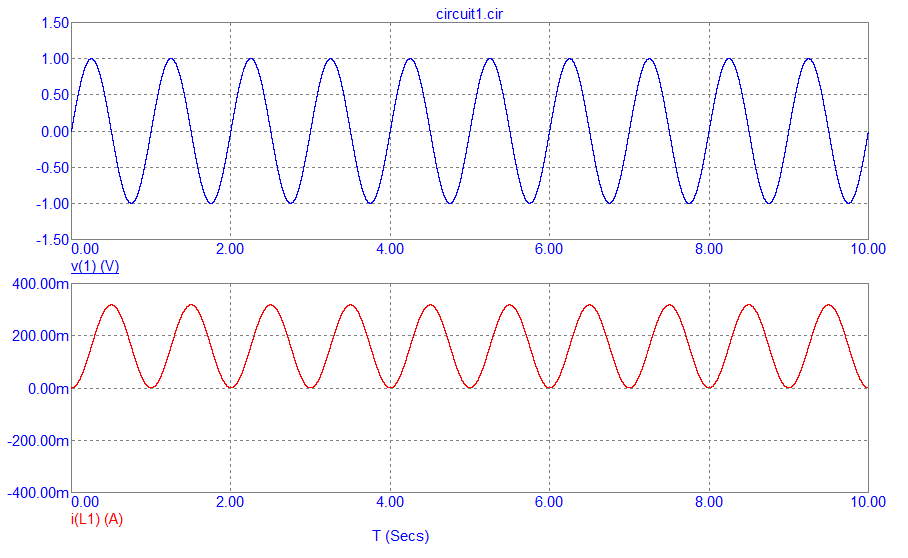
The result is correct; you get a term that is the AC impedance of the inductor and, a term that represents the instantaneous phase angle of the applied voltage when it is first powered. Consider this simulation using a sinewave voltage of 1 volt peak across a 1 henry inductor: -

enter image description here

As you can see, the current contains the usually expected alternating part but, it is also raised above 0 amps by a DC value. This is what happens when you drive an inductor with a sinewave voltage where the phase angle is 0° at the point of activation of the sinewave.

In other words, the DC term above represents the phase angle of the voltage source when that voltage source was first applied. 0° means a big DC offset; 90° means no DC offset. Your derivation is probably correct but, you just don't believe it can be so.

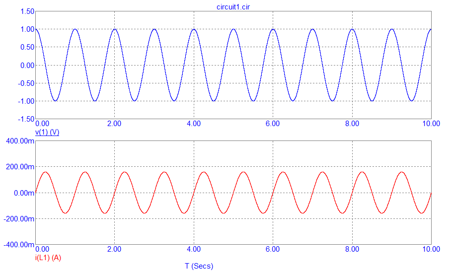
So, if you activated the sinewave at 90°, you just get the AC waveform with no DC offset: -

enter image description here

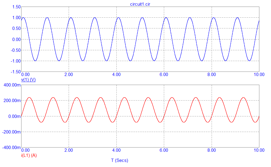
At 45° it looks like this: -

enter image description here

And all of this is caused by the act of integration right back at the start of your formulas. It's also the reason why many transformers heavily saturate when first powered-on (a real-life problem). Anti-inrush current circuits are used in real-life to activate the voltage at the top of its waveform.

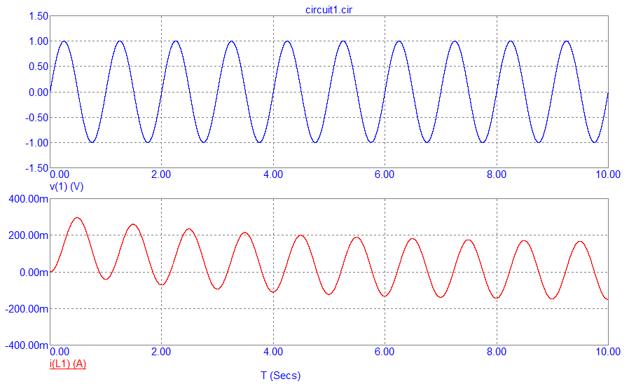
Of course, a real inductor (lossy) soon finds equilibrium such as when a sinewave is applied at 0° but in series with 0.3 ohms: -

enter image description here

But for many cycles, this can and does cause breakers to trip on transformer feeds.

\$\endgroup\$
0
2
\$\begingroup\$

Phase requires a reference phase. The input phase is arbitrary, so it can be set to zero without loss of generality. (If the input phase is different from zero, use the trig identities for sin(A+B) and cos(A+B).) You must restrict your integral to period boundaries,

The result of your integral becomes:$$i(t)=\frac{V_{m}}{\omega}sin(\omega t)$$

EDIT (Response to ozgun can comment below):

Impedance is not a time domain quantity. It is a frequency domain qualtity. In fact the most general form for impedance is expressed in the Laplace domain which removes the sinusoidal constraint. It cannot be obtained directly fwom a time domain integral without transformation in to the frequency domain.

END EDIT

A simpler approach is to use Euler's form: $$v_{L}=V_{m}e^{j(\omega t+\phi)}$$ This allows the input phase to be factored out: $$v_{L}=V_{m}e^{j\phi}e^{j\omega t}$$ Then the integral for the inductor current for \$i_{L}(0)=0\$ is: $$i_{L}=\frac{V_{m}}{j\omega}e^{j\phi}e^{j\omega t}$$ The input phase then cancels out of the impedance ratio: $$\frac{v_{L}}{i_{L}} = j\omega L$$

Of course the Laplace transform method works as well. The Laplace transform converts the defining relation from time domain into the complex frequency domain which allows the most general expression for impedance in that it applies to all signals not just sinusoids.

The Laplace transform of the defining relation with zero initial conditions is:

$$V_{L}(s)=sLI_{L}(s)$$ $$Z(s)=\frac{V_{L}(s)}{I_{L}(s)}=sL$$ $$Z(j\omega)=j\omega L$$

\$\endgroup\$
5
  • \$\begingroup\$ the phase of the voltage is needed to be there to make it more general case, it can not be assumed zero because the phase means, for example, if you were to plug your circuit to power socket in your house, you cant be sure, the moment you plugged in, the voltage starts from some arbitrary value which determines, according to my calculation, the characteristics. in short, the time you give voltage source affects the current characteristics, which shouldn't be \$\endgroup\$
    – ozgun can
    Commented Sep 18, 2022 at 13:20
  • \$\begingroup\$ That would be a different problem. There will be a transient solution that must die out before the result can be used for calculating impedance. When using signals to calculate the impedance of a component they must be in steady state. This allows picking the phase reference arbitrarily. The signal must be sinusoidal. For several cycles after plugging in the signal is not sinusoidal. \$\endgroup\$
    – user319836
    Commented Sep 18, 2022 at 13:40
  • \$\begingroup\$ what I am interested in, whether can u find the impedance of inductor by using definite integral containing the time variable within its integral boundary, because , that is the most physical(realistic) form of the equation, aside from its derivative form. \$\endgroup\$
    – ozgun can
    Commented Sep 18, 2022 at 13:43
  • \$\begingroup\$ @ozguncan: Impedance is not a time domain quantity. It is a frequency domain quantity. I cannot be obtained directly from a time domain integral. See my edit \$\endgroup\$
    – user319836
    Commented Sep 18, 2022 at 14:19
  • \$\begingroup\$ @ozguncan: You may have success if you restrict your integration to period boundaries \$\endgroup\$
    – user319836
    Commented Sep 18, 2022 at 14:51
1
\$\begingroup\$

You have to use complex voltage source \$V_s(t) = V_m e^{j(ωt+θ)}\$. Then you use kirchoff's voltage law in the circuit.

Current in the the circuit is \$i(t) = I_me^{j(ωt+Φ)}\$.This is a assumption. Let \$Z_L\$ be impedance of the inductor.The values of \$I_m\$ and Φ can be calculated by using KVL, phasor notation and initial conditions.

Applying KVL in the loop,

$$-V_s(t) + L\frac{di}{dt} =0$$

$$V_s(t) = L\frac{di}{dt}$$

$$V_me^{(j(ωt+θ)} = L\frac{di}{dt} I_me^{j(ωt+Φ)}$$

$$V_m e^{j(ωt+θ)} = jωLI_me^{j(ωt+Φ)}$$

Dividing LHS and RHS by \$e^{jwt}\$

$$V_me^{jθ} = jωLI_me^{jΦ} $$

Voltage across the inductor should be same as voltage across the voltage source.

Therefore \$V_L\$ = jωLI which is similar to the expression \$V_L\$ = \$Z_L\$I. So,impedance \$Z_L\$ of the inductor is jωL.

\$\endgroup\$
10
  • 2
    \$\begingroup\$ Welcome Amit, Please edit your answer using the equation editor. It makes much more readable equations. \$\endgroup\$
    – user319836
    Commented Sep 18, 2022 at 13:12
  • \$\begingroup\$ Dont know how to use the equation editor. Once I do, I will rewrite the answer in a more readable format. Thanks. \$\endgroup\$
    – Amit M
    Commented Sep 18, 2022 at 13:16
  • 1
    \$\begingroup\$ @Amit Here is an excellent resource. \$\endgroup\$ Commented Sep 18, 2022 at 13:23
  • 1
    \$\begingroup\$ I see you keep on editing your answer but, you ignored @RussellH's suggestion, and the link I provided. By now there are 15 edits, none regarding the suggestions. If you're going to take that much time to edit then, at the very least, you could try to be more in line with the site's overall guide lines. \$\endgroup\$ Commented Sep 18, 2022 at 13:40
  • \$\begingroup\$ The equations editor seems not functioning if I type something as \font {di}{dt} for di/dt when I type the formatting in code as above. \$\endgroup\$
    – Amit M
    Commented Sep 18, 2022 at 13:43

Your Answer

By clicking “Post Your Answer”, you agree to our terms of service and acknowledge you have read our privacy policy.

Not the answer you're looking for? Browse other questions tagged or ask your own question.