2
\$\begingroup\$

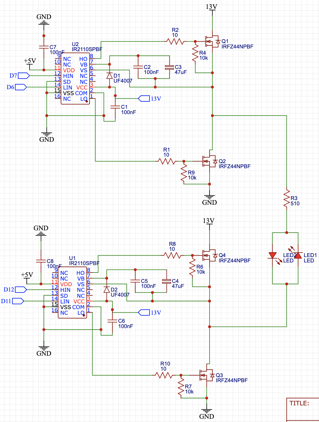
Here is my circuit:

enter image description here

When I start on phase 1 by PWMing LIN & HIN of U2 and send a HIGH signal to LIN of U1, then the circuit works perfectly and only one LED lights up.

When I try to switch to phase 0 (after starting on phase 1) by PWMing LIN & HIN of U1, and send a HIGH signal to LIN of U2, then the MOSFET bridge suddenly shorts and breaks both of my IR2110 ICs.

BUT if I turn my DC power supply down to 0 V, reset the Arduino to start on phase 1, and turn the DC power supply back up to 13 V then the other LED lights up without a problem.

For some reason my MOSFETs are only shorting when I try to switch phases; if I start on either phase 1 or phase 0 then it works perfectly.

Does anyone know why this would happen? I am implementing 10 μs of dead time between switching phases so I don't think shoot-through would be the problem.

Here is the code I am running:

byte preg = 2;
byte sec = 0;
byte pres = 0;

void setup() {
  pinMode(D7, OUTPUT);
  pinMode(D6, OUTPUT);
  pinMode(D12, OUTPUT);
  pinMode(D11, OUTPUT);
  digitalWrite(D7, LOW);
  digitalWrite(D6, LOW);
  digitalWrite(D12, LOW);
  digitalWrite(D11, LOW);
  // A5 is connect to a button so I can switch phases when 
  // pressing the button
  pinMode(A5, INPUT);
  // I have an LED attached to A0 to help me keep track of 
  // button presses
  pinMode(A0, OUTPUT);
  digitalWrite(A0, LOW);
}

void loop() {
  // This code is to debounce a button press when for switching 
  // phases
  sec = digitalRead(A5);
  if (sec == 0) {
    // Wait 1 second to check if button is still pressed
    delay(1000);
    sec = digitalRead(A5);
    if (sec == 0) {
      pres = digitalRead(A0);
      if (pres == 1) {
        // Set phase 0
        preg = 0;
      } else if (pres == 0) {
        // Set phase 1
        preg = 1;
      }
    }
  }
  
  // Switch to the new phase when button is pressed
  switch(preg) {
    // Phase 0
    case 0:
      digitalWrite(D7, LOW);
      digitalWrite(D6, LOW);
      digitalWrite(D12, LOW);
      digitalWrite(D11, LOW);
      digitalWrite(A0, LOW);
      delayMicroseconds(10);
      analogWrite(6, 100);
      for (int i = 0; i < 10000; i++) {
        phase0();
      }
        break;
    // Phase 1
    case 1:
    digitalWrite(D7, LOW);
    digitalWrite(D6, LOW);
    digitalWrite(D12, LOW);
    digitalWrite(D11, LOW);
    digitalWrite(A0, HIGH);
    delayMicroseconds(10);
    analogWrite(11, 100);
    for (int x = 0; x < 10000; x++) {
      phase1();
    }
      break;
  }
}

// PWM U1 LIN & HIN alternatively to charge C4 & C5
void phase0() {
  digitalWrite(11, HIGH);
  digitalWrite(12, LOW);
  delayMicroseconds(10);
  digitalWrite(11, LOW);
  digitalWrite(12, LOW);
  delayMicroseconds(1);
  digitalWrite(11, LOW);
  digitalWrite(12, HIGH);
  delayMicroseconds(150);
  digitalWrite(11, LOW);
  digitalWrite(12, LOW);
  delayMicroseconds(1);
}
// PWM U2 LIN & HIN alternatively to charge C2 & C3
void phase1() {
  digitalWrite(6, HIGH);
  digitalWrite(7, LOW);
  delayMicroseconds(10);
  digitalWrite(6, LOW);
  digitalWrite(7, LOW);
  delayMicroseconds(1);
  digitalWrite(6, LOW);
  digitalWrite(7, HIGH);
  delayMicroseconds(150);
  digitalWrite(6, LOW);
  digitalWrite(7, LOW);
  delayMicroseconds(1);
}
\$\endgroup\$
8
  • 1
    \$\begingroup\$ Is that really a 510ohm resistor, because if it has inductance that's a problem \$\endgroup\$
    – Voltage Spike
    Commented Nov 18, 2022 at 6:11
  • \$\begingroup\$ Why are you using analogWrite(6,100) and (11,100)? Is that 100% PWM or setting the pins high? Otherwise it's hard to translate the binary port digitalWrite instructions. You must make sure that you set all the drive inputs LOW before changing phase. \$\endgroup\$
    – PStechPaul
    Commented Nov 18, 2022 at 7:41
  • \$\begingroup\$ <<< When I start on phase 1 by PWMing LIN & HIN of U2, and send a HIGH signal to LIN of U1 >>> ... Are you really sending PWM on the two inputs Lin & Hin of the same IC? If you are PWMing HIN, then LIN of the same IC must be at low level ... PWM are applied to HIN and levels are applied on LIN. \$\endgroup\$
    – Antonio51
    Commented Nov 18, 2022 at 19:42
  • \$\begingroup\$ @Antonio51 yes I am sending PWM to LIN & HIN of the same IC. I just updated my code and as you can see in the phase0() and phase1() functions, the LIN and HIN pins should never be on at the same time because I have added a 1us delay between each PWM & I turn one of them off while the other one is on. \$\endgroup\$
    – Trev347
    Commented Nov 18, 2022 at 20:33
  • 2
    \$\begingroup\$ You have C3 and C4 as 47 uF, which is much too large. It should be somewhere around 100 nF to 1 uF. The bypass capacitors C1 and C8 could be augmented with 47 uF capacitors. Also, your PWM using analogWrite(6) and (11) require the opposite high side drive (D12 or D7) to be ON, and that requires its bootstrap to provide gate current for 150 us. The bootstrap capacitor probably has not had enough time to fully charge (you have 10 us low drive). \$\endgroup\$
    – PStechPaul
    Commented Nov 18, 2022 at 22:21

3 Answers 3

3
\$\begingroup\$

Finally figured this out after a lot of trial and error. Turns out the problem is my code. If you do analogWrite(pin, value), then try to turn the PWM off with port manipulation using PORTD / PORTB then the analogWrite will stay on and it is not effected by the port manipulation.

You need to instead do digitalWrite(pin, LOW), or analogWrite(pin, LOW) and it will turn off the PWM.

Edit:

In the answer i'm not using PORT manipulation in my code because I was trying to make it easier for people to read, but on my actual project i was using PORT manipulation so it was a problem.

\$\endgroup\$
0
\$\begingroup\$

The IR2110 cannot maintain a continuous "HI" output, the bootstrap capacitor will quickly (less than 1 second) discharge through the 10k resistor.

You've used a blocking delay so the MCU goes off into never-never land for at least one second when the switch is pressed and the previous MCU outputs (whatever they are) are maintained,

I don't know if that's your problem, but I think it's something that needs to be fixed. Better to use a hardware timer for debouncing. Also, 1 second is very long for debouncing, 10ms is adequate, but I think you'd need different logic- I think the way you have it now it just toggles back and forth every second as long as the switch is pressed.

\$\endgroup\$
2
  • \$\begingroup\$ These are some good things to consider. TBH I was just lazy with my debouncing button so I should probably fix that, but I still don't think this is the main problem. Even if my MCU goes off into "never-never land" and the capacitor discharges completely, then that shouldn't make the MOSFETs short. If anything it would just make the top MOSFET turn off which would prevent a short. \$\endgroup\$
    – Trev347
    Commented Nov 18, 2022 at 21:27
  • \$\begingroup\$ If the undervoltage lockout does not work properly, the upper MOSFET could enter a linear region where it will function as a resistor, but I doubt that is your problem. It would be better to use a complementary PWM pair on the Arduino to drive one half-bridge, with the low side of the opposite half-bridge driven low. This might help: forum.arduino.cc/t/complementary-pwm-channels-output/567009/9 It might be easier to use a half-bridge driver with shoot-through protection like IR2103. \$\endgroup\$
    – PStechPaul
    Commented Nov 18, 2022 at 22:54
0
\$\begingroup\$

For reference.

EE&O ...

The H-bridge driven by IR2110 (and others) has four "phases" for working.
Can be simplified .. Link.

LIN1 and LIN2 are High. HIN1 and HIN2 are Low. "Brake" phase LOW.
LIN1 and LIN2 are Low. HIN1 and HIN2 are PWM_ON. "Brake" phase HIGH.
LIN1 is High and HIN2 is PWM_ON, LIN2 is Low and HIN1 is Low: motor "rotate" "left".
LIN1 is Low and HIN2 Low, LIN2 is High and HIN1 is PWM_ON: motor "rotate" "left".

\$\endgroup\$
1
  • \$\begingroup\$ This is what I was doing previously and someone told me it would not work. You need to charge the bootstrap capacitors by sending a complimentary PWM signal to HIN1 & LIN1. For example - LIN1 & HIN1 are PWM_ON, LIN2 is HIGH and HIN2 is LOW. While sending PWM to LIN1 & HIN1 only 1 of them can be HIGH while the other one is LOW which charges the capacitor, then you need to implement dead time between switching them to prevent shoot through. Check Bryan's comment in this post: electronics.stackexchange.com/questions/641733/… \$\endgroup\$
    – Trev347
    Commented Nov 18, 2022 at 21:45

Your Answer

By clicking “Post Your Answer”, you agree to our terms of service and acknowledge you have read our privacy policy.

Not the answer you're looking for? Browse other questions tagged or ask your own question.