4
\$\begingroup\$

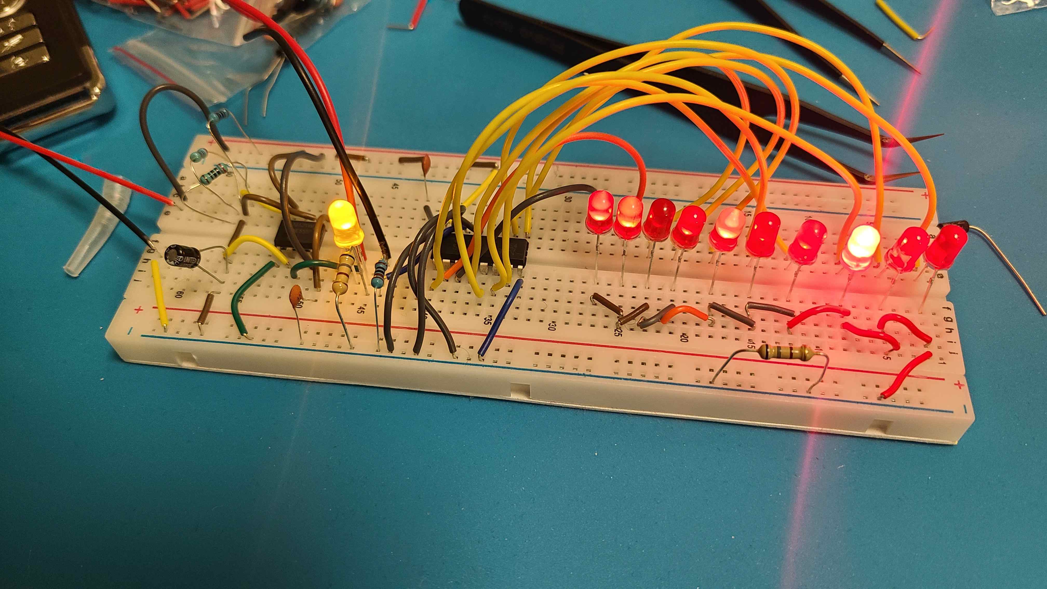
I know it will not be easy to answer just by looking at this.

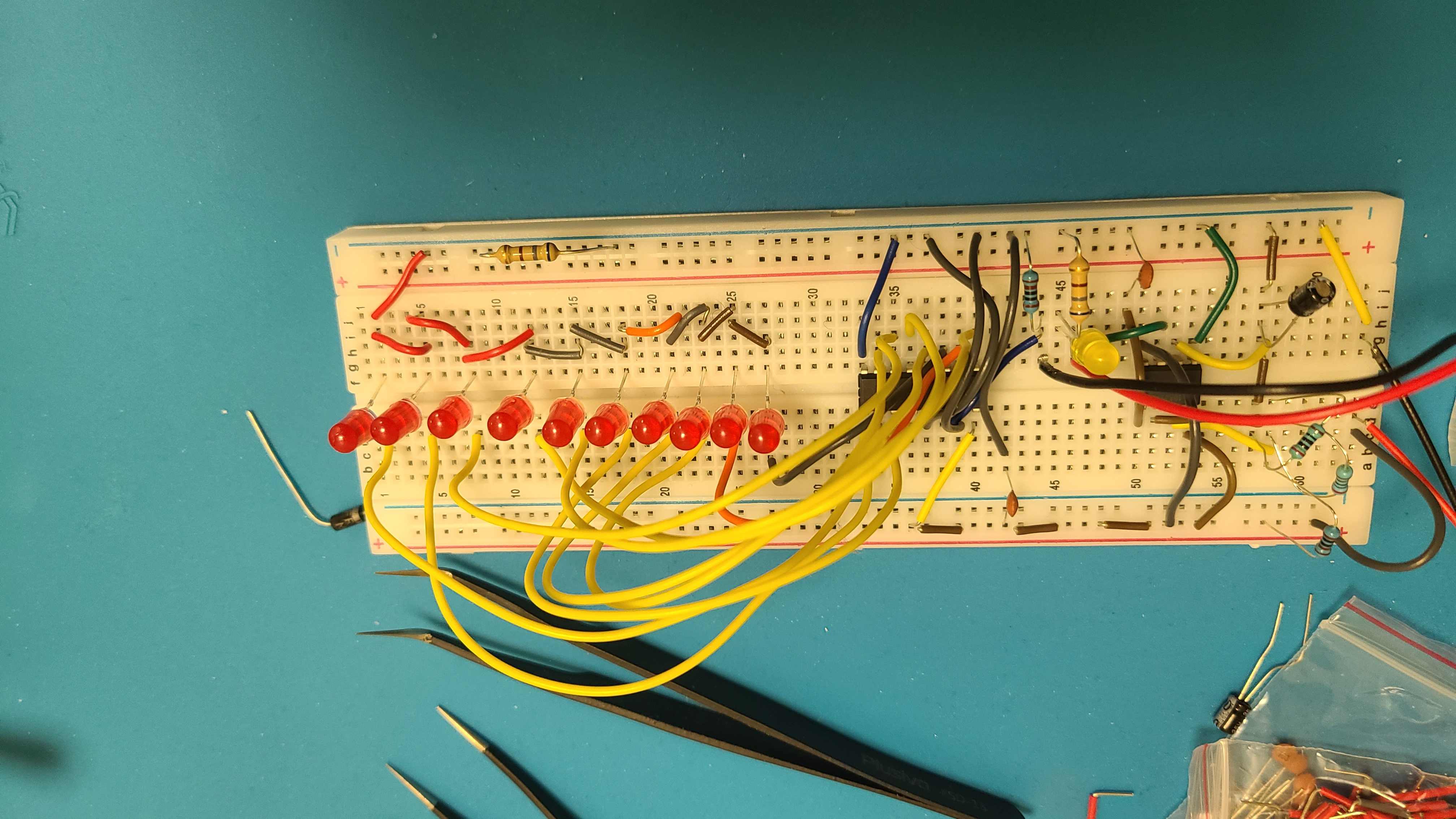
The breadboard instructions in the book are fully wrong; it doesn't work at all.

Then I tried building according to the circuit diagram. All it's doing is lighting up.

Check this video please.

I used a 2 kΩ resistor and a 200 Ω resistor for 2.2 kΩ.

enter image description here

enter image description here

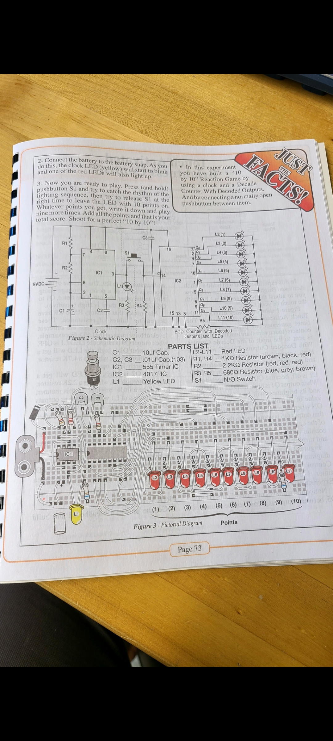
This is the instruction:

enter image description here

\$\endgroup\$
3
  • \$\begingroup\$ Does L1 flash? If not then the 555 oscillator is not working. \$\endgroup\$
    – Russell McMahon
    Commented Nov 19, 2022 at 5:52
  • \$\begingroup\$ It does work. The rest of light is not blinking \$\endgroup\$
    – Obiick
    Commented Nov 19, 2022 at 15:52
  • \$\begingroup\$ I asked if L1 FLASHED. You said it WORKED. Work MAY mean that it lit but did not flash. With C1 connected as you have it it seems impossible that the LED would flash. But, perhaps it does. Does it flash - that is, turn on and off repeatedly? \$\endgroup\$
    – Russell McMahon
    Commented Nov 22, 2022 at 7:49

4 Answers 4

15
\$\begingroup\$

When starting out, we all made many mistakes, that is part of the normal process of learning. You have some mistakes, so try not to get too discouraged. Let me point out a couple of issues, in addition to what has already been said.

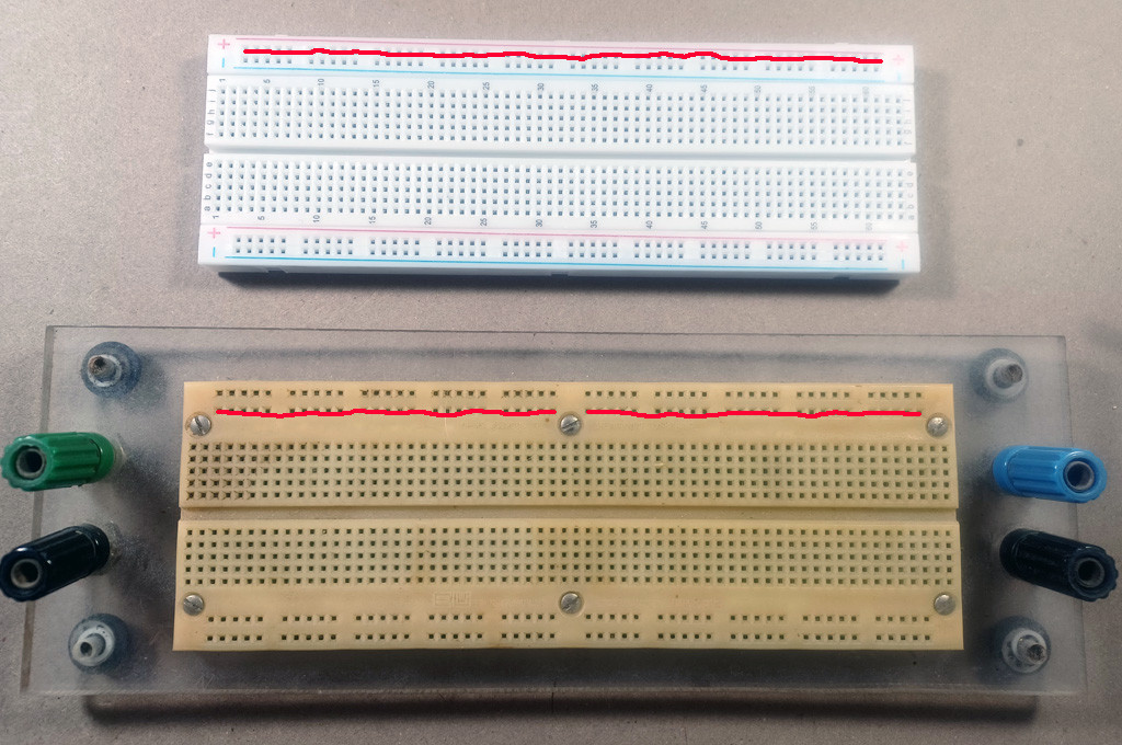
First, not all breadboards are the same. The one that you show is probably one of the most common ones today and they can be found everywhere. The "rails", positive and negative run the length of those rows so all of the little sockets are connected for each rail (shown in the top picture). The breadboard appearing in the workbook is an older style (bottom picture) and the rails are interrupted at one point and have to be bridged with a jumper wire and you see that in the diagram.
enter image description here

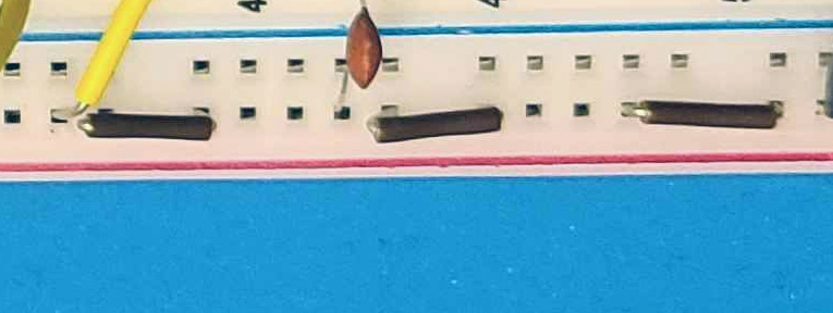
You don't need to add that jumper and you probably don't need to add three such jumpers shown below from your picture. BUT, get a meter and check how your breadboard is laid out - that way you don't have to guess.
enter image description here

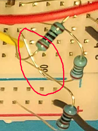
Second, look carefully at these resistors. Some of the leads look like they are touching and that will cause you some problems. Either trim the leads or make sure they don't touch each other.
enter image description here

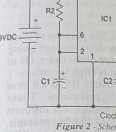
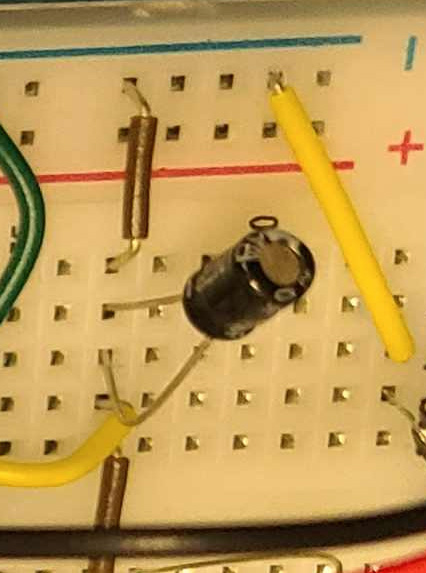
Next look at C1 in the schematic.

enter image description here

Now look at your board - see the difference? You have the + and - leads connected together and that is going to be a problem.
enter image description here

To make matters even more confusing, in the manual's pictorial illustration, it looks like they left C1 unconnected and off to the side - that happens and it is extra tough when it does and you are just starting out.

You might not want to hear this, but I think the best thing is to rebuild the whole circuit and do it slowly and carefully AND keep asking questions.

One of the hardest of all the lessons I had to learn is to check everything before applying power. Believe me, we ALL learn that lesson and I hope that you will keep at it because when you finally see the circuit working, it feels great!

\$\endgroup\$
3
  • 8
    \$\begingroup\$ "One of the hardest of all the lessons I had to learn is to check everything before applying power" Twenty years later, I can still smell that 7805 melting! \$\endgroup\$
    – Dan
    Commented Nov 19, 2022 at 18:41
  • \$\begingroup\$ Thank you so much. It is so informative. I changed everything according to your saying and now I connected the negative side of the capacitor directly to the terminal negative. But it is still not working. How to fix it \$\endgroup\$
    – Obiick
    Commented Nov 19, 2022 at 18:41
  • 1
    \$\begingroup\$ Magic Smoke \$\endgroup\$ Commented Nov 20, 2022 at 15:42
8
\$\begingroup\$

S1 needs debouncing, and there is no power supply decoupling on the schematic or near the power pins of the ICs in the assembly. Other than that the schematic looks ok. I think your problems are in your assembly, not the design

In your assembly, the resistor in the top left corner of image #1 is not placed correctly. All of the sockets in the red and blue rows along the top and bottom edges of a proto board are connected together, effectively shorting out the resistor. This means the 4017 is sinking way too much current, and might already be damaged.

\$\endgroup\$
3
  • 1
    \$\begingroup\$ If its damaged then I am gone. I have only one 4017. You are sucha nice person to take the time and guide me . Thank you so much \$\endgroup\$
    – Obiick
    Commented Nov 19, 2022 at 15:05
  • \$\begingroup\$ Could you please tell me how to fix the schematic and the resistor? \$\endgroup\$
    – Obiick
    Commented Nov 19, 2022 at 15:07
  • \$\begingroup\$ seeing as this is CMOS, the easiest way to debounce is to remove R4 \$\endgroup\$ Commented Nov 20, 2022 at 2:35
4
\$\begingroup\$

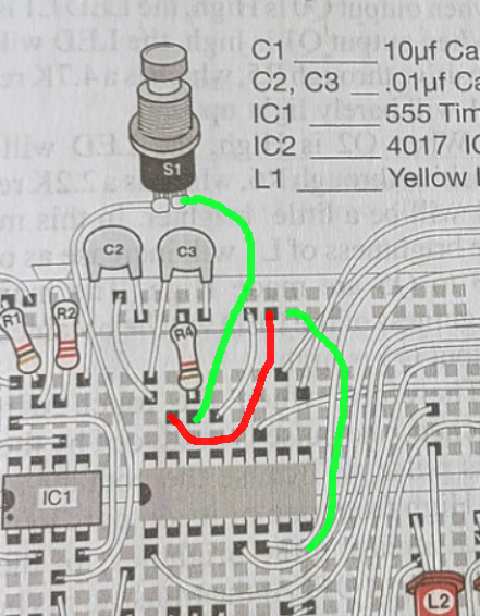
The diagram in the book is missing three wires.

enter image description here

\$\endgroup\$
6
  • \$\begingroup\$ Except that do u think its all good? I build by looking at the circuit diagram \$\endgroup\$
    – Obiick
    Commented Nov 19, 2022 at 20:40
  • 4
    \$\begingroup\$ At this point, you don't know if the 4017 or the 555 has been damaged - but you can test them. Here is a simple circuit to test the 4017 - You have everything to do this. circuitdiagram.org/led-chaser-using-cd-4017.html Remove all other components from the board and see if you can get this to work. If so, we can come up with something for the 555. DIVIDE AND CONQUER :) \$\endgroup\$
    – DrG
    Commented Nov 19, 2022 at 22:21
  • \$\begingroup\$ I feel like I damaged it but I will check this now. Thank you so much. I will get back to you \$\endgroup\$
    – Obiick
    Commented Nov 20, 2022 at 2:32
  • \$\begingroup\$ these parts are fairly durable, \$\endgroup\$ Commented Nov 20, 2022 at 2:34
  • \$\begingroup\$ Here is the update : I have made a circuit like that with that IC and none of the bulb was lightening. \$\endgroup\$
    – Obiick
    Commented Nov 20, 2022 at 5:52
0
\$\begingroup\$

I was using a wrong IC instead of 4017 that's why it was not working

\$\endgroup\$
1
  • \$\begingroup\$ So it works OK now? \$\endgroup\$
    – PStechPaul
    Commented Nov 27, 2022 at 5:41

Your Answer

By clicking “Post Your Answer”, you agree to our terms of service and acknowledge you have read our privacy policy.

Not the answer you're looking for? Browse other questions tagged or ask your own question.